Transformer winding with efficient heat dissipation structure

A technology of transformer winding and heat dissipation structure, applied in transformer/inductor coil/winding/connection, transformer/inductor cooling, transformer/inductor components, etc., can solve the problem of poor heat dissipation effect of iron core winding

Active Publication Date: 2021-05-11
鑫大变压器有限公司
View PDF10 Cites 0 Cited by
  • Summary
  • Abstract
  • Description
  • Claims
  • Application Information

AI Technical Summary

Problems solved by technology

[0004] Aiming at the deficiencies of the prior art, the present invention provides a transformer winding with a high-efficiency heat dissipation structure,

Method used


Image

  • Transformer winding with efficient heat dissipation structure
  • Transformer winding with efficient heat dissipation structure
  • Transformer winding with efficient heat dissipation structure

Examples


Embodiment 1

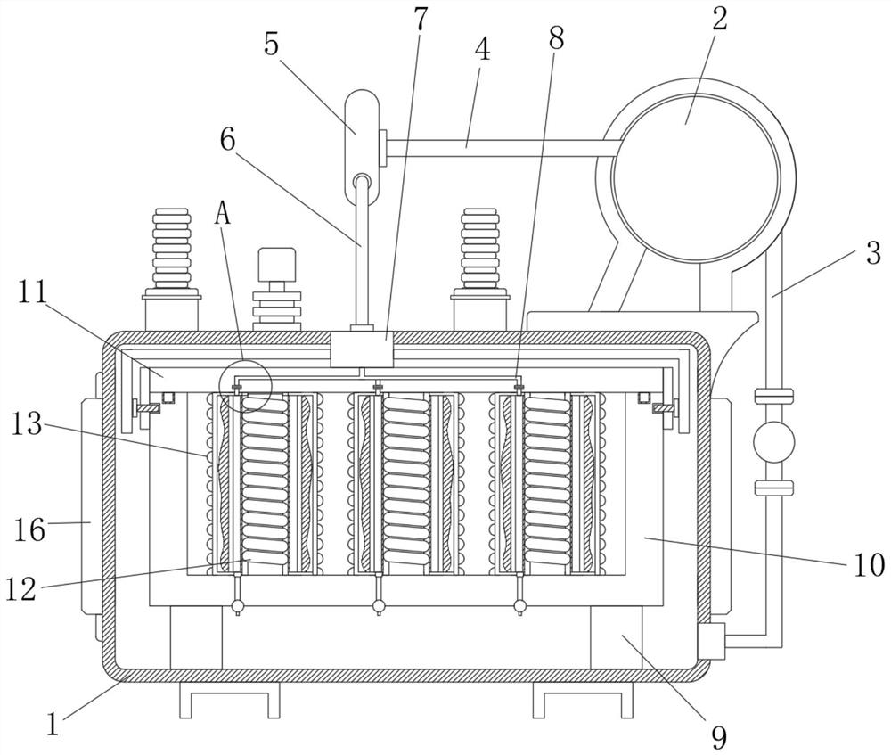
[0029] see figure 1 , Figure 4 , Figure 5 , Figure 6 , Figure 7 , including a tank 1, a fuel tank 2 is installed on the right side of the top of the tank 1, the bottom of the fuel tank 2 is fixedly connected with an oil delivery pipe 3, the oil delivery pipe 3 is connected with the inner wall of the tank 1, and the left side of the fuel tank 2 is fixedly communicated with an outlet The oil pipe 4 and the left side of the oil outlet pipe 4 are equipped with a guide box 5, the bottom of the guide box 5 is fixedly connected with a connecting pipe 6, and the bottom of the connecting pipe 6 is fixedly connected with a splitter box 7, and the splitter box 7 is fixedly connected to the inner wall of the box body 1. The top, the bottom of the inner wall of the box body 1 is fixedly connected with two legs 9, the top of the legs 9 is fixedly connected with a frame 10, the top of the frame 10 is open, and the top of the frame 10 is equipped with an upper cover 11, the upper cover...

Embodiment 2

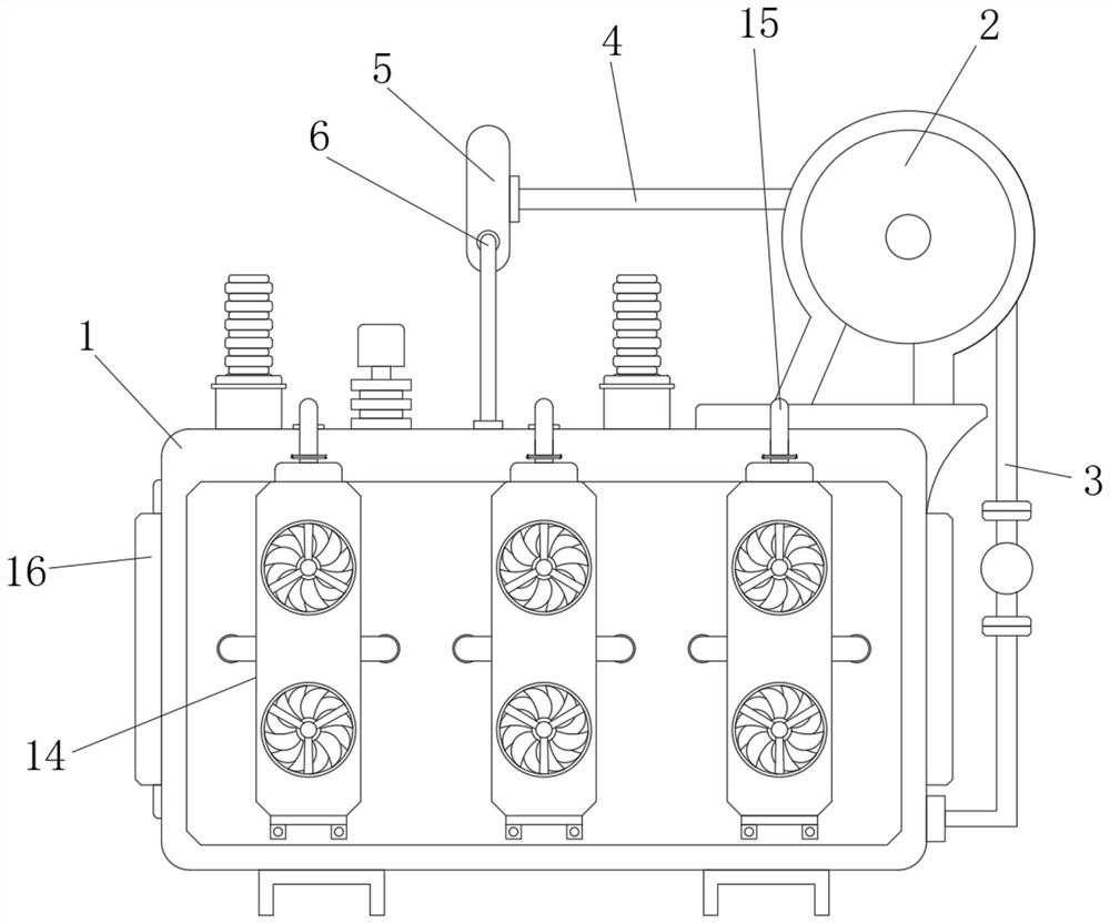
[0033] see figure 2 and image 3 , the front of the box body 1 is equipped with three external heat dissipation mechanisms 14, the top of the external heat dissipation mechanism 14 is fixedly connected with three exhaust pipes 15, the exhaust pipe 15 is connected with the inner wall of the box body 1, and the top of the box body 1 is provided with several Air vent, outer cooling mechanism 14 comprises object board 141, and the front of object board 141 is provided with two fans for heat dissipation, and object board 141 is fixedly connected with the front of casing 1 by the support bar 142 of left and right sides.

[0034] Through the above structural design, the staff can also dissipate heat from the inside of the box 1 through the fan, and extract the hot air in the box 1 through the exhaust pipe 15, and cooperate with the oil-immersed heat dissipation method to make the overall heat dissipation effect of the device Even better, there are more ways to dissipate heat.

Embodiment 3

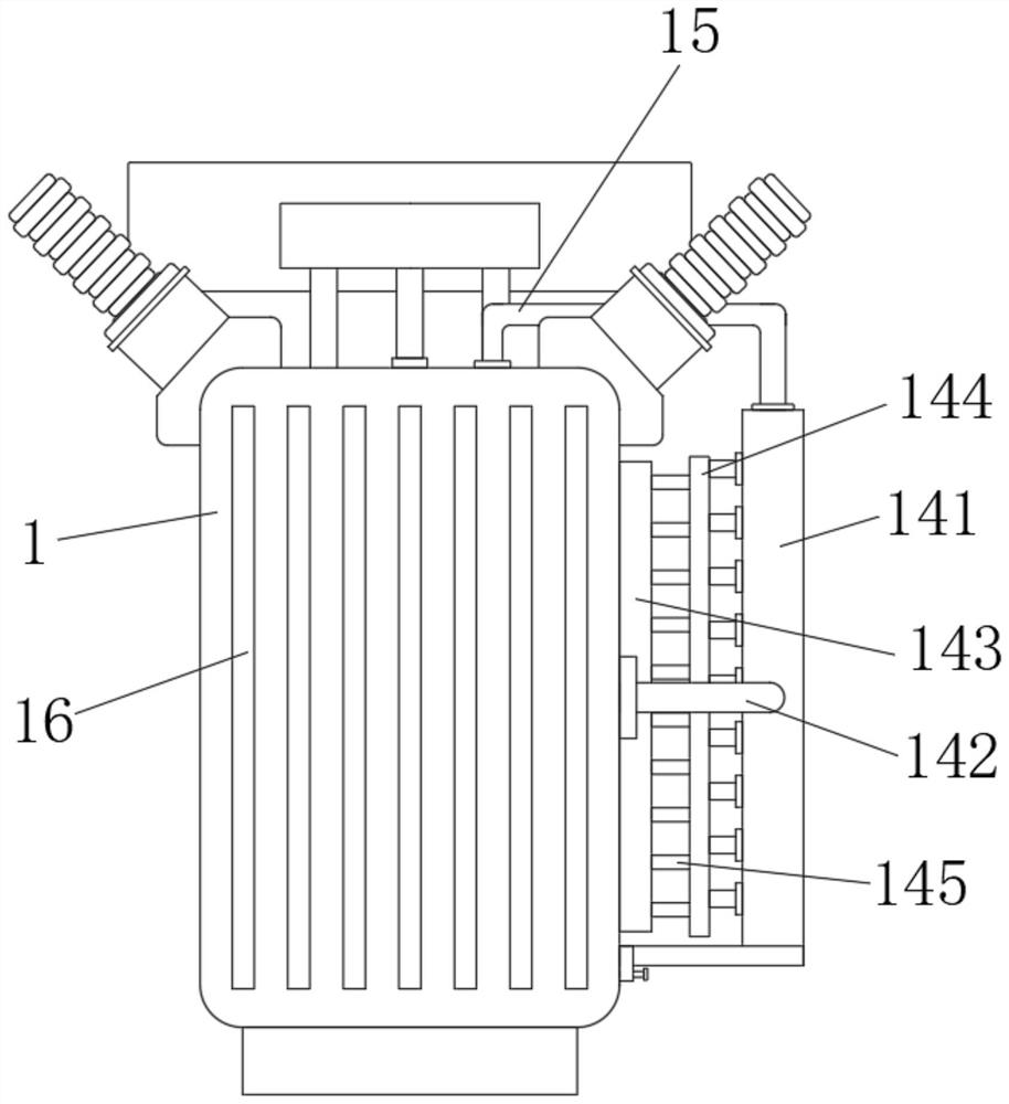
[0036] see image 3The back of the storage plate 141 is fixedly connected with a connecting rod 145, the back of the connecting rod 145 is fixedly connected with a connecting plate 144, and the back of the connecting plate 144 is fixedly connected with a fitting plate 143, and the back of the fitting plate 143 is attached to the front of the box body 1 Fitting, laminating plate 143, connecting rod 145 and connecting plate 144 are all made of copper, and the left and right sides of splitter box 7 are fixedly communicated with two oil inlet pipes 8, and this oil inlet pipe 8 is used for injecting oil in casing 1.

[0037] Through the above-mentioned structural design, the laminated plate 143 can absorb the temperature on the surface of the box body 1, so as to dissipate heat on the surface of the box body 1, cooperate with the heat dissipation of the upper fan and the exhaust pipe 15, and heat the surface of the box body 1 and the surface of the box body 1. The inner wall dissip...


PUM


Abstract

The invention relates to the technical field of transformers, and particularly discloses a transformer winding with an efficient heat dissipation structure, which comprises a box body. Two supporting legs are fixedly connected to the bottom of the inner wall of the box body, a frame body is fixedly connected to the tops of the supporting legs, the top of the frame body is open, and an upper cover body is mounted at the top of the frame body; three iron core windings are installed between the bottom of the upper cover body and the top of the frame body, three insulation cooling protection mechanisms are installed on the surfaces of the three iron core windings, and the iron core windings are arranged in the insulation cooling protection mechanisms. Through the arrangement of the insulation cooling protection mechanism, cooling oil can be shunted after entering the box body through the oil tank, one part of the oil is injected into the box body, and the other part of the oil can flow into the space between the inner heat conduction plate and the outer ring baffle, so that heat dissipated by the iron core winding can be transmitted through the inner heat conduction plate and is taken away by oil in contact with the inner heat conduction plate, and the heat dissipation effect is achieved.

Description

technical field [0001] The invention relates to the technical field of transformers, and specifically relates to a transformer winding with a high-efficiency heat dissipation structure. Background technique [0002] A power transformer is a static electrical device that is used to change an AC voltage of a certain value into another voltage with the same frequency or several voltages with different values. When the primary winding is supplied with alternating current, an alternating current The alternating magnetic flux, through the magnetic conduction of the iron core, induces an AC electromotive force in the secondary winding. The level of the secondary induced electromotive force is related to the number of turns of the primary and secondary windings, that is, the voltage and the number of turns Proportional. [0003] When the transformer is running, the heat generated by the loss of the winding and the core must be dissipated in time to avoid insulation damage caused by...

Claims


Application Information

Patent Timeline
IPC IPC(8): H01F27/14H01F27/08H01F27/28
CPCH01F27/14H01F27/2876H01F27/085
Inventor 李君
Owner 鑫大变压器有限公司
Why Eureka
Try Eureka