Supercharge Your Innovation With Domain-Expert AI Agents!

Rail vehicle electric door travel switch trigger device

A travel switch and rail vehicle technology, applied in the field of rail transit, can solve the problems of unstable and reliable triggering and release, and achieve the effect of saving labor costs, saving workload, stable and reliable triggering and releasing

Pending Publication Date: 2021-05-11
沈阳博得交通设备有限公司 +1
View PDF0 Cites 0 Cited by
  • Summary
  • Abstract
  • Description
  • Claims
  • Application Information

AI Technical Summary

Problems solved by technology

[0006] Compared with the prior art, the beneficial effect of the present invention is: the trigger device of the rail vehicle electric door travel switch, the trigger device is a cam rotary structure, the rotating bumper is a transition device between the moving bumper and the travel switch, and the rotating bumper It is in direct contact with the limit switch, and the relative position of the two is guaranteed by the processing tolerance, which is relatively accurate. Although the assembly error of the door and the car body will affect the position of the moving bumper, it will only bring the initial position of the rotating bumper and the position of the bumper. The change of the relative angle of the working position will not affect the trigger stroke of the switch, which can realize the stable and reliable trigger and release of the travel switch, solve the problem of unsteady and reliable trigger and release of the switch, and can offset the assembly error of the door and the car body when installing the stroke The impact of switch triggering avoids the adjustment of the position of the door travel switch during maintenance and maintenance, saves the workload required for switch adjustment, saves labor costs, and is compact in structure, easy to use, maintain and repair. It is a rail vehicle Stable and reliable mechanical structure triggered by electric door travel switch

Method used


Image

  • Rail vehicle electric door travel switch trigger device
  • Rail vehicle electric door travel switch trigger device
  • Rail vehicle electric door travel switch trigger device

Examples


Embodiment Construction

[0011] The following will clearly and completely describe the technical solutions in the embodiments of the present invention with reference to the accompanying drawings in the embodiments of the present invention. Obviously, the described embodiments are only some, not all, embodiments of the present invention. Based on the embodiments of the present invention, all other embodiments obtained by persons of ordinary skill in the art without making creative efforts belong to the protection scope of the present invention.

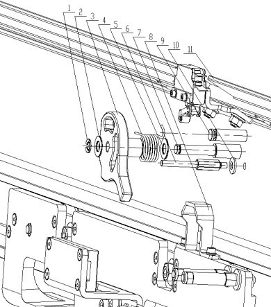
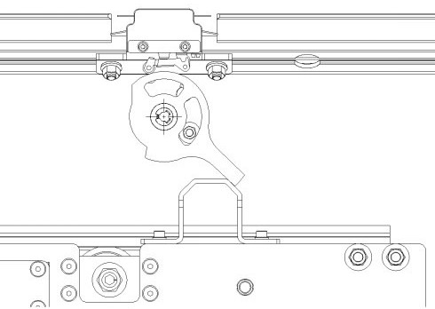
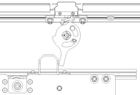
[0012] see Figure 1-3 , the present invention provides a technical solution: a trigger device for a travel switch of an electric car door of a rail vehicle, including a mounting base plate 11 and an electric car door. A travel switch, a central shaft 7 is provided below the travel switch, and the central shaft 7 is fixedly connected to the installation base plate 11, and the outer wall of the central shaft 7 is sequentially movably socketed with a first washe...


PUM


Abstract

The invention discloses a rail vehicle electric door travel switch trigger device which comprises a mounting bottom plate and an electric door, a movable collision block is fixedly connected to the upper portion of the electric door, the travel switch is fixedly connected to the upper portion of the front face of the mounting bottom plate, and a center shaft is arranged below the travel switch and fixedly connected with the mounting bottom plate. The outer wall of the center shaft is movably sleeved with a first gasket, a rotary collision block and a second gasket in sequence. According to the rail vehicle electric door travel switch trigger device, the trigger device is of a cam rotary structure, the rotary collision block is a transition device of the movable collision block and the travel switch and makes direct contact with the travel switch, the relative position of the rotary collision block and the travel switch is guaranteed through machining tolerance and is relatively accurate, and although the position of the moving collision block is influenced due to the assembly errors during installation of the vehicle door and a vehicle body, only the relative angle change of the initial position and the working position of the rotating collision block is brought, and the trigger stroke of the switch is not influenced.

Description

technical field [0001] The invention relates to the technical field of rail transit, in particular to a trigger device for a travel switch of an electric door of a rail vehicle. Background technique [0002] In recent years, all walks of life in the field of rail transit in my country have experienced rapid development, especially the rapid development of the subway and light rail industries. At present, there are more than 300 main lines in operation in major and medium-sized cities across the country; among them, there are dozens of subways, light rails, and intercity vehicles that shuttle on each line. Doors are one of the most important parts of a rail vehicle, with thousands of sets per line. As we all know, delays and disconnections caused by operational failures of rail vehicles (mainline operating vehicles, returned to the warehouse for maintenance due to operational failures) will cause a large number of passengers to be stranded, with huge negative impacts, which ...

Claims


Application Information

Patent Timeline
IPC IPC(8): H01H3/16
CPCH01H3/161
Inventor 曹华飞
Owner 沈阳博得交通设备有限公司
Features
  • R&D
  • Intellectual Property
  • Life Sciences
  • Materials
  • Tech Scout
  • Unparalleled Data Quality
  • Higher Quality Content
  • 60% Fewer Hallucinations
Learn More