Wire harness fixing and protecting device for machine vision detection

A machine vision inspection and wire harness fixing technology, applied in electrical components and other directions, can solve the problems of wire harness falling off, pulling, easy to bend, etc., to prevent bending, reduce friction, and quickly adjust the guiding orientation.

Pending Publication Date: 2021-05-11
GUILIN UNIV OF ELECTRONIC TECH
View PDF0 Cites 1 Cited by
  • Summary
  • Abstract
  • Description
  • Claims
  • Application Information

AI Technical Summary

Problems solved by technology

[0003] The machine vision inspection system includes multiple wire harnesses used to collect and transmit signals. During work, the wire harnesses are usually scattered or organized by simple bundling. The wire harnesses are prone to fall off or be damaged by scratches. Will be pulled, prone to bending

Method used


Image

  • Wire harness fixing and protecting device for machine vision detection
  • Wire harness fixing and protecting device for machine vision detection
  • Wire harness fixing and protecting device for machine vision detection

Examples


Embodiment 1

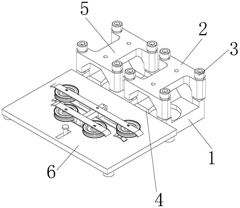
[0028] see figure 1 , the present invention provides a wire harness fixing protection device for machine vision detection through improvement, including a base 1, a first cover plate 2, bolts 3, slots 4, a second cover plate 5 and a wire management mechanism 6, the base 1 The bolt 3 is locked and fixed with the bottom of the first cover 2, and the cable management mechanism 6 is installed and fixed on the front end of the base 1. The upper ends of the base 1 and the first cover 2 are provided with slots 4, and the left end of the top of the base 1 is provided with a second cover. plate 5.

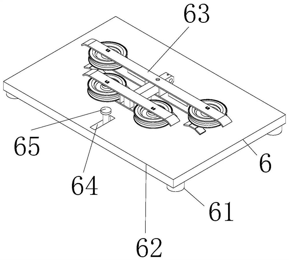
[0029] see figure 2 , the present invention provides a wire harness fixing and protection device for machine vision inspection through improvement. 62 is fixedly connected with the front end of the base 1, the fixed frame 62 is fixed with the bottom four corners of the anti-skid block 61, the top of the fixed frame 62 is provided with a guide wheel mechanism 63, the front end of the top ...

Embodiment 2

[0033] The present invention provides a fixed protection device for machine vision detection wire harness through improvement. The fixed frame 62 is in the shape of a cuboid with an inner cavity, which is beneficial to install and fix the rotation limiting mechanism 65. The first cover plate 2 and the second cover plate The two cover plates 5 have the same size, and the first cover plate 2 and the second cover plate 5 are distributed parallel to each other, which is beneficial to fix the wiring harness.

[0034] The present invention provides a fixed protection device for machine vision detection wire harness through improvement, and its working principle is as follows;

[0035] First, before use, place the wire harness fixing protection device for machine vision detection horizontally, so that the base 1 and the anti-slip block 61 can fix and support the device;

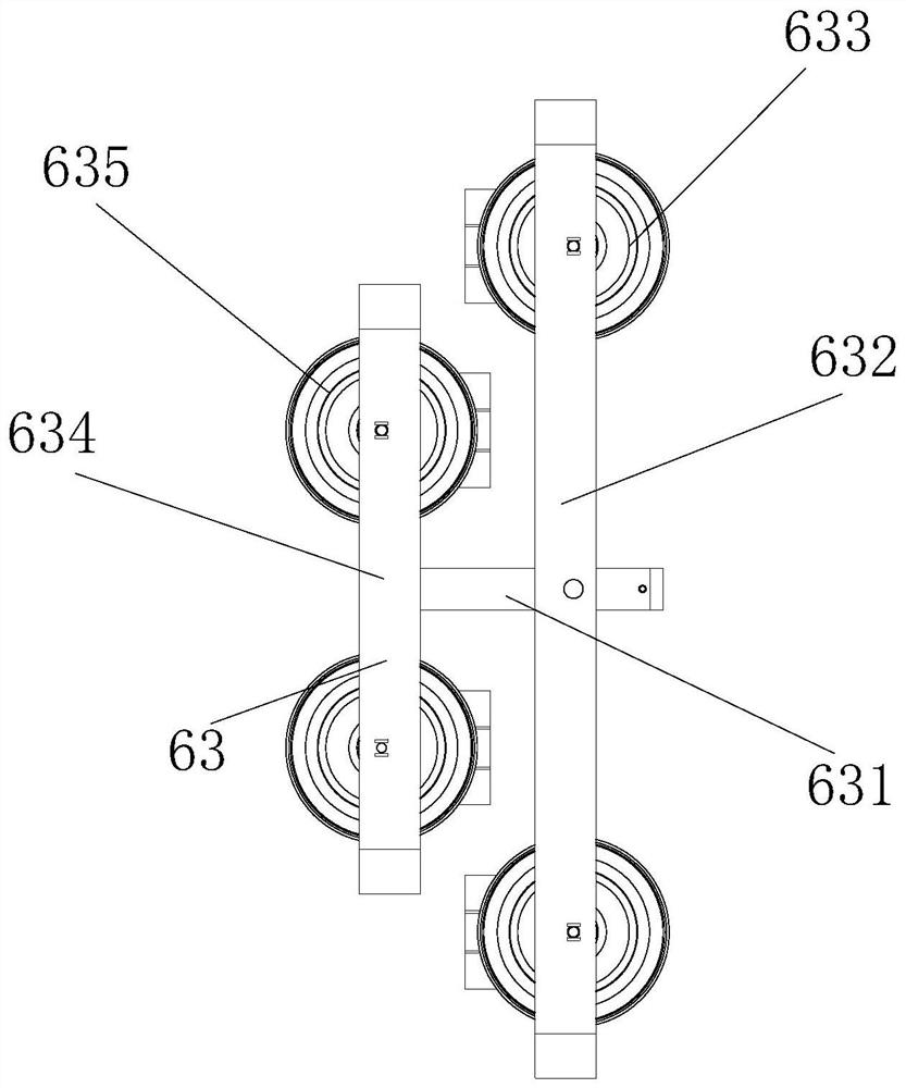
[0036] Second, when in use, pass a plurality of wire harnesses through the inside of the first cross bar 632 and ...


PUM


Abstract

The invention discloses a wire harness fixing and protecting device for machine vision detection, which comprises a base, a first cover plate, a bolt, a slot, a second cover plate and a wire arranging mechanism. The wire arranging mechanism is arranged at the front end of the base, and a plurality of wire harnesses respectively penetrate through the inner sides of a first cross rod and a second cross rod; the first roller and the second roller are in contact with one ends, close to the connecting rod, of the first roller and the second roller, so that the wire harnesses are separately placed, and the advantages of reducing friction force at the upper ends of the wire harnesses and preventing the wire harnesses from being bent are achieved; the rotating limiting mechanism is arranged at the upper end of the wire arranging mechanism, the connecting rod is shifted to rotate around the rotating shaft, and the advantage that the guide direction of the guide wheel mechanism can be rapidly adjusted is achieved.

Description

technical field [0001] The invention specifically relates to a wire harness fixing and protection device for machine vision detection, and relates to the related field of machine vision. Background technique [0002] Machine vision is a branch of artificial intelligence that is rapidly developing. Simply put, machine vision is to use machines instead of human eyes for measurement and judgment. Machine vision systems use machine vision products (ie, image capture devices, which are divided into CMOS and CCD) ) to convert the captured target into an image signal and send it to a dedicated image processing system. [0003] The machine vision inspection system includes multiple wire harnesses used to collect and transmit signals. During work, the wire harnesses are usually scattered or organized by simple bundling. The wire harnesses are prone to fall off or be damaged by scratches. It will be pulled and prone to bending. Contents of the invention [0004] Therefore, in orde...

Claims


Application Information

Patent Timeline
IPC IPC(8): H02G3/04
CPCH02G3/0406
Inventor 陆佳琪梅枫杨龙梁晨光
Owner GUILIN UNIV OF ELECTRONIC TECH
Why Eureka
Try Eureka