
Mill support and medical craniotomy device thereof

A technology of milling cutter holder and milling cutter, which is applied in the field of medical equipment and can solve problems such as heat generation, loud noise and vibration

Inactive Publication Date: 2021-05-14
CHONGQING YIXI BRAND PLANNING CO LTD
View PDF5 Cites 0 Cited by
  • Summary
  • Abstract
  • Description
  • Claims
  • Application Information

AI Technical Summary

Problems solved by technology

In actual use, the milling cutter is directly driven by a motor, and the rotation of the motor will generate large noise, vibration and heat, and the milling cutter will also generate heat when cutting the skull, which makes the milling cutter easy to overheat and cause secondary damage to the patient. harm
In addition, the vibration and noise of the motor will interfere with the medical staff, especially the vibration, which can easily fatigue the hand held by the operator, thus causing greater physical exertion to the medical staff.

Method used


Image

  • Mill support and medical craniotomy device thereof
  • Mill support and medical craniotomy device thereof
  • Mill support and medical craniotomy device thereof

Examples


Embodiment Construction

[0035] The following will clearly and completely describe the technical solutions in the embodiments of the present invention with reference to the drawings in the embodiments of the present invention.

[0036] In describing the present invention, it should be understood that the terms "upper", "lower", "front", "rear", "left", "right", "top", "bottom", "inner", " The orientation or positional relationship indicated by "outside", etc. is based on the orientation or positional relationship shown in the drawings, and is only for the convenience of describing the present invention and simplifying the description, rather than indicating or implying that the referred device or element must have a specific orientation, so as to Specific orientation configurations and operations, therefore, are not to be construed as limitations on the invention.

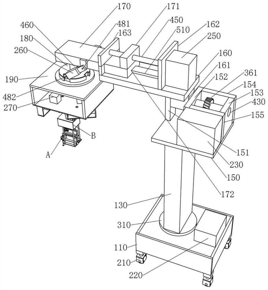
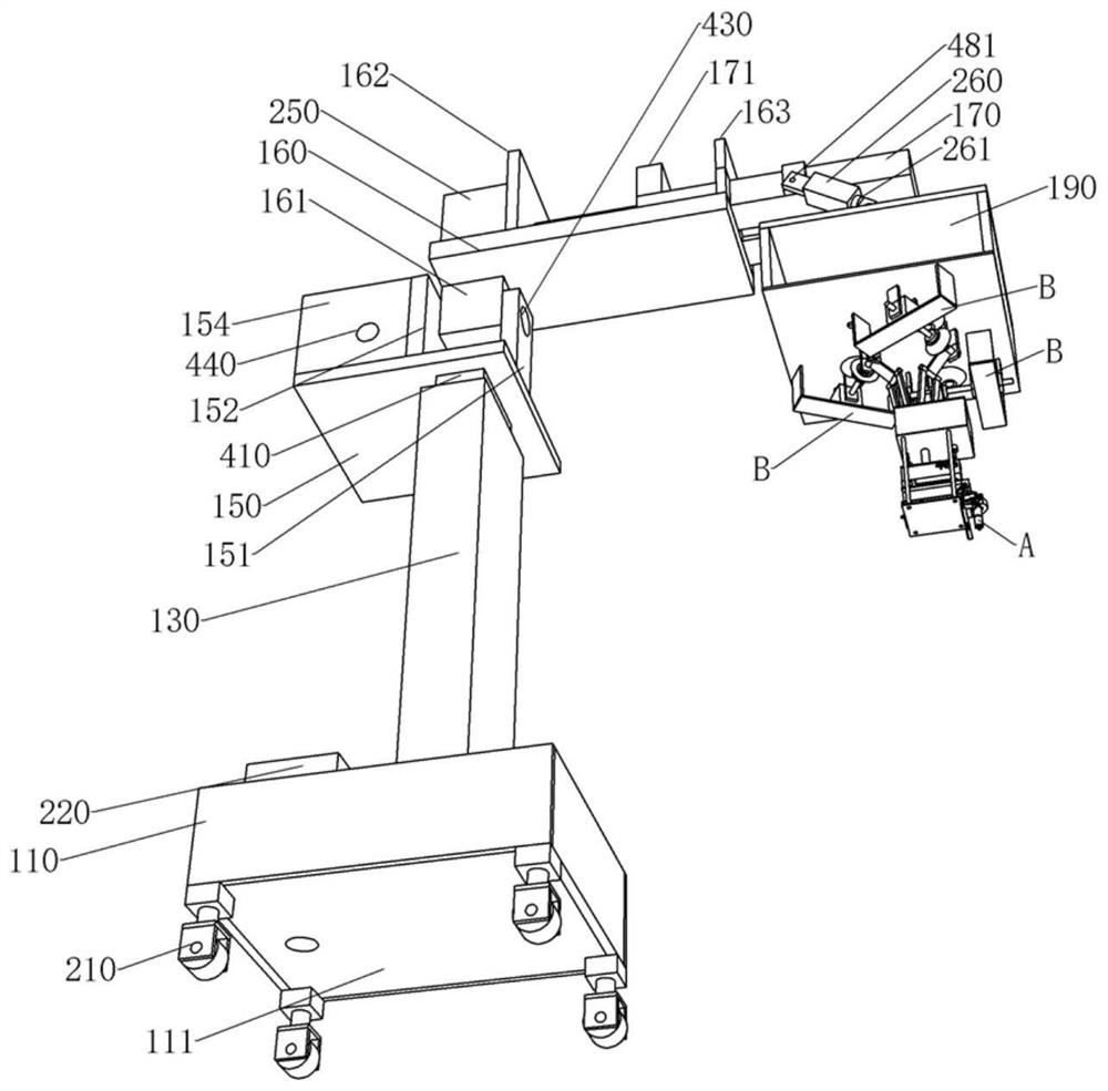
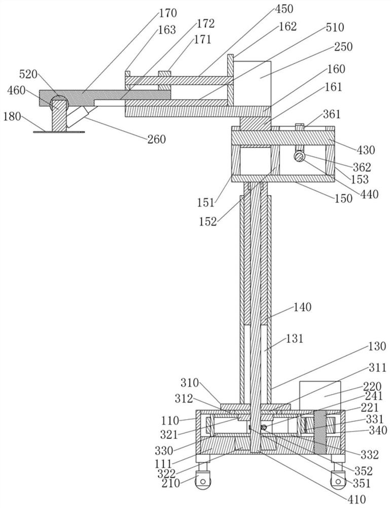
[0037] see Figure 1-Figure 28 , the medical craniotomy device of the present embodiment comprises a base 110, and a universal wheel 210...


PUM


Abstract

The invention provides a mill support and a medical craniotomy device thereof. The medical craniotomy device comprises a connecting frame, wherein the connecting frame is installed on a moving frame; the moving frame comprises a moving bottom plate; at least three mechanical claw mechanisms are installed on the moving bottom plate; each mechanical claw mechanism comprises a moving motor, a second movable vertical plate, a third movable vertical plate and a clutch telescopic shaft; a clutch cylinder is provided with second clutch teeth; the second clutch teeth and a clutch sliding block are assembled in a separable mode, the second clutch teeth and first clutch teeth are in meshing transmission, and the first clutch teeth are installed in a movable motor shaft; the clutch cylinder is installed at one end of a clutch rotating shaft, and the other end of the clutch rotating shaft penetrates through the two third movable vertical plates and can be assembled with the two third movable vertical plates in a circumferential rotation mode; the clutch rotating shaft is fixedly assembled with one end of a first mechanical arm, and the other end of the first mechanical arm is hinged to one end of a second mechanical arm through a mechanical arm shaft; the other end of the second mechanical arm is assembled with a mechanical claw block through a hinge ball; the mill support is installed on the mechanical claw block; a milling head module is installed on the mill support; and a milling cutter is installed on the milling head module.

Description

technical field [0001] The invention relates to medical equipment, in particular to a medical craniotomy device. Background technique [0002] Craniotomy is an operation in which the head is cut open to treat the brain. The operation steps are generally: 1. Cut the scalp; 2. Cut the skull; 3. Cut the dura mater; 4 perform the operation; 5. Suture the dura mater, skull and scalp one by one. [0003] At present, craniotomy is one of the commonly used brain surgeries, which usually takes more than 2-8 hours, and a lot of time is wasted on skull incision. The incision of the skull is generally made by drilling three holes at the cutting site, and then cutting and connecting the three holes with a milling cutter, so that the complete skull can be taken out. In actual use, the milling cutter is directly driven by a motor, and the rotation of the motor will generate large noise, vibration and heat, and the milling cutter will also generate heat when cutting the skull, which makes...

Claims


Application Information

Patent Timeline
Patent Type & Authority Applications(China)
IPC IPC(8): A61B17/16A61B17/17A61B34/00A61B34/20A61B34/30A61B90/00A61B90/50B08B15/04
CPCA61B17/1626A61B17/1631A61B17/1659A61B17/1695A61B17/1703A61B17/1739A61B2017/00017A61B2217/002A61B34/20A61B34/30A61B34/70A61B90/06A61B90/361A61B90/37A61B90/50A61B2034/2055A61B2034/2065A61B2034/2072A61B2090/061B08B15/04
Inventor 袁素
Owner CHONGQING YIXI BRAND PLANNING CO LTD
Learn More