Medical instrument for otolaryngology department
A medical appliance and otolaryngology technology, applied in the field of otolaryngology, can solve the problems of increased working pressure, inconvenient adjustment, unfavorable operation, etc., and achieve the effect of convenient fixation, guaranteeing the stability of the operation, and avoiding movement.
- Summary
- Abstract
- Description
- Claims
- Application Information
AI Technical Summary
Problems solved by technology
Method used
Image

Examples
Embodiment 1
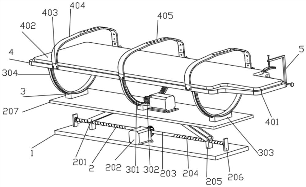
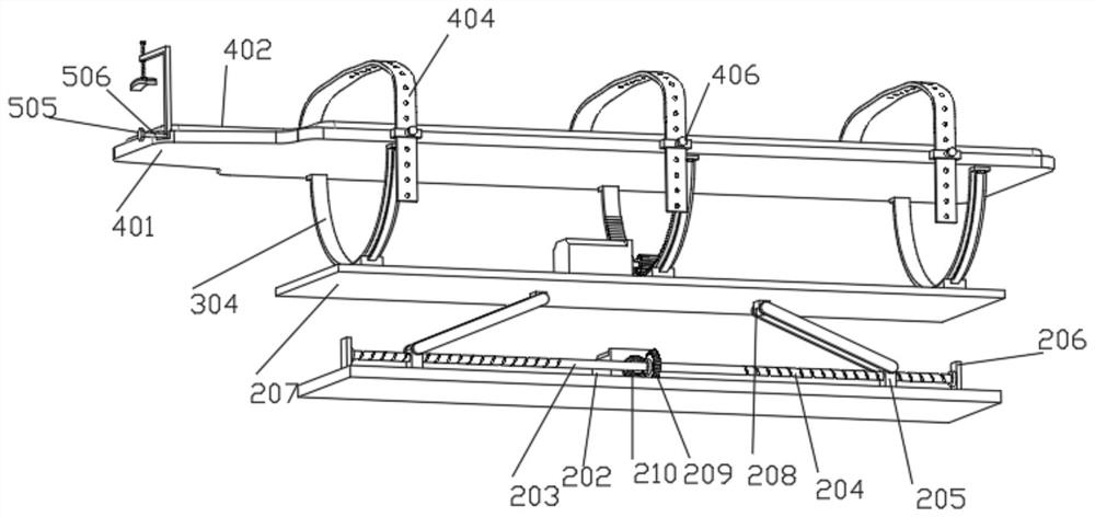
[0041] Such as figure 1 , 2, 3, 4, and 8 show a medical appliance for ENT, including a base plate 1, characterized in that: the top of the base plate 1 is provided with a height adjustment structure 2 for height adjustment, and the height adjustment structure 2 includes a rotating plate 201, First driving motor 202, rotating rod 203, screw groove 204, slide plate 205, straight plate 206, movable plate 207, straight block 208, first bevel gear 209 and second bevel gear 210, straight plate 206 is connected by the bearing that is fixedly connected with Rotating rod 203, the rotating rod 203 is symmetrically provided with thread grooves 204, and the rotating rod 203 is symmetrically threaded through the thread grooves 204 to be connected with a slide plate 205 that is fitted and slidably connected to the top of the bottom plate 1, and the rotating shaft that is fixedly connected to the top of the slide plate 205 is rotatably connected to a rotating plate 201, the top of the rotat...
Embodiment 2
[0043] Embodiment 2 is a further improvement to Embodiment 1.
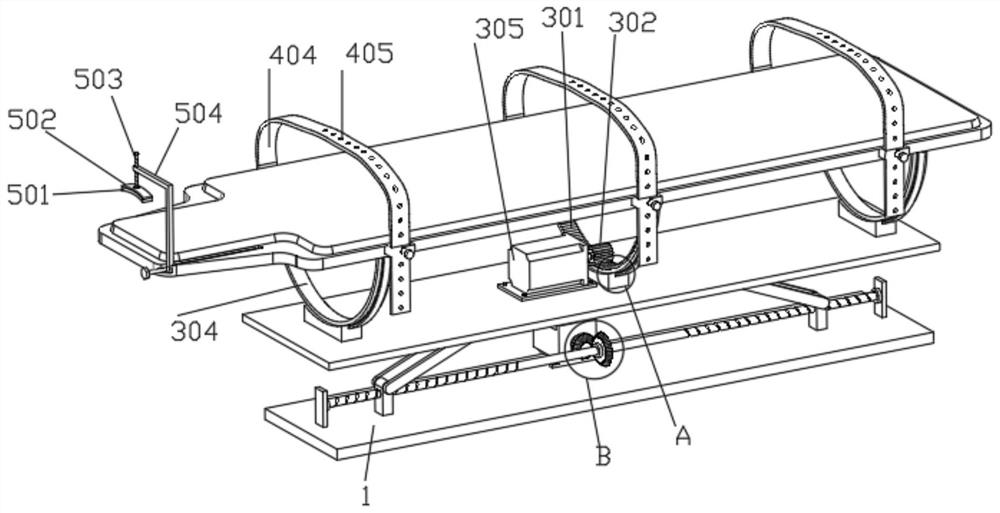
[0044] Such as figure 1 , 3 , 4, 7, and 9, the top of the movable plate 207 is provided with a rotating structure 3 for body rotation, and the rotating structure 3 includes a gear block 301, a ring gear 302, a support plate 303, an arc plate 304, and a second drive motor 305 , limit slider 306, arc groove 307 and limit chute 308, support plate 303 is evenly fixedly installed on the top of movable plate 207, and the top of support plate 303 is provided with arc groove 307, and the side wall of arc groove 307 The arc plate 304 is fixedly connected, and the support plate 303 is fitted and slidably connected with the arc plate 304 through the arc groove 307. Both side walls of the arc plate 304 are provided with limit chute 308, and the inner wall of the limit chute 308 is connected to the The outer wall of the limit slider 306 is fitted and slidably connected, and the second drive motor 305 is fixedly installed at ...
Embodiment 3
[0046] Embodiment 3 is a further improvement to Embodiment 1.
[0047] Such as figure 1 , 2 , 3, 5, 6, and 10, the top of the curved plate 304 is connected with a fixed support structure 4 for body fixation, and the fixed support structure 4 includes a support plate 401, a sponge plate 402, a connecting block 403, a strap 404, a positioning Hole 405, latch 406, spring 407 and U-shaped block 408, the two ends of arc plate 304 are symmetrically fixedly installed on the bottom of support plate 401, and the top of support plate 401 is fixedly connected with the sponge plate 402 that is used for weakening hard force, and support plate One side wall of 401 is uniformly fixedly connected with connecting block 403 by fixing bolts, and the top of connecting block 403 is fixedly connected with strap 404, and strap 404 is evenly provided with positioning hole 405, and the other side wall of support plate 401 is on the connecting block 403 The corresponding position of the U-shaped bloc...
PUM
 Abstract
Description
Claims
Application Information