Supercharge Your Innovation With Domain-Expert AI Agents!

Physical polishing device for laboratory

A laboratory and physical technology, applied in grinding drives, grinding machines, grinding racks, etc., can solve problems such as waste of resources, scrapped grinding wheels, and inability to move grinding wheels, saving costs, prolonging service life, avoiding The effect of the fixed position of the grinding wheel

Inactive Publication Date: 2021-05-14
王子东
View PDF11 Cites 1 Cited by
  • Summary
  • Abstract
  • Description
  • Claims
  • Application Information

AI Technical Summary

Problems solved by technology

[0004] The purpose of the present invention is to provide a physical grinding device for laboratories, which can solve the problem that the grinding wheel cannot be moved in the background technology, so that only the middle position of the grinding wheel is relied on when grinding the workpiece. Once the intermediate body of the grinding wheel is worn, the entire grinding wheel It is scrapped and can no longer be used, resulting in a technical problem of waste of resources

Method used


Image

  • Physical polishing device for laboratory
  • Physical polishing device for laboratory
  • Physical polishing device for laboratory

Examples


Embodiment 1

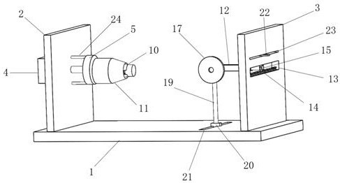
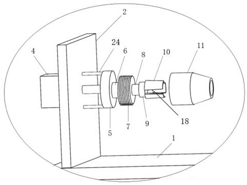
[0032] Such as Figure 1-4As shown, a physical grinding device for laboratory use includes a base 1, and the base 1 is provided with a first side plate 2 and a second side plate 3, and the board surface of the first side plate 2 and the second side plate 3 is arranged correspondingly, the first side plate 2 is provided with a cylinder 4, the rod of the cylinder 4 is connected with a clamping mechanism, and the clamping mechanism includes a first round platform 5, and the first round platform 5, one side is fixedly connected with the rod of the cylinder 4, and the other side is connected with a threaded platform 7 through the first connecting piece 6, and the side of the threaded platform 7 away from the first circular platform 5 is connected with the second connecting piece 8 through the second connecting piece 8. Two round tables 9, in order to make the clamping mechanism more stable, the first round table 5, the first connector 6, the threaded table 7, the second connector 8...

Embodiment 2

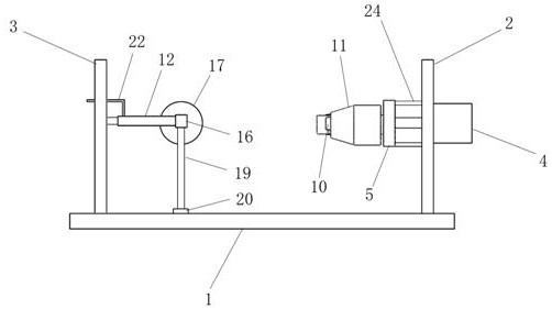
[0035] Same as Example 1, the difference is: as Figure 1-2 As shown, the bottom of the hood 16 is connected with a support column 19, and the end of the support column 19 away from the hood 16 is connected with a slider 20, and the base 1 is provided with a slideway matched with the slider 20. twenty one. By setting the support column 19 at the bottom of the machine cover 16, it is beneficial to support the weight of the second motor and the grinding wheel 17, preventing the grinding wheel 17 from shifting downward under the action of gravity and affecting the grinding effect; the support column 19 is slidably connected to the base through the slider 20 1, it is beneficial to cooperate with the left and right movement of the grinding wheel 17 when working.

Embodiment 3

[0037] Same as Example 1, the difference is: as Figure 1-2 As shown, the connecting rod 12 is a square structure, the upper end of the connecting rod 12 is connected with a guide plate 22, the guide plate 22 is L-shaped, and the second side plate 3 is provided with a 22 is matched with the guide groove 23, the length of the guide groove 23 is equal to the length of the rectangular frame 13, and the inner diameter of the guide groove 23 matches the outer diameter of the guide plate 22. By setting the L-shaped guide plate 22, and the L-shaped guide plate 22 cooperates with the guide groove 23 on the second side plate 3, it is beneficial to prevent the position deviation of the connecting rod 12 when moving in the horizontal direction, so that the structure of the device is more stable.

[0038] Working principle: a physical grinding device used in the laboratory. Under normal conditions, the bite mouth 11 is threadedly connected with the thread table 7. By loosening the bite mo...


PUM


Abstract

The invention relates to a physical polishing device for a laboratory, and relates to the technical field of physical experiment equipment. The physical polishing device comprises a base, a first side plate and a second side plate are arranged on the base, an air cylinder is arranged on the first side plate, and a rod part of the air cylinder is connected with a clamping mechanism; and a connecting rod is arranged at the side, opposite to the clamping mechanism, of the second side plate, the connecting rod is of a hollow structure, a rectangular frame is formed in the second side plate, a rack is arranged in the rectangular frame, a gear is arranged on the rack, a first motor is connected to the gear, the first motor is arranged in one end of the connecting rod; and the other end of the connecting rod is connected to a machine cover, a second motor is arranged in the machine cover, and a grinding wheel is connected to an output shaft of the second motor. The physical polishing device is simple in structure and high in practicability, workpieces of different sizes can be clamped, the grinding wheel can be driven to move left and right, and the situations that the position of the grinding wheel is fixed, grinding is carried out only through the center position of the grinding wheel, and the service life of the grinding wheel is shortened are avoided.

Description

technical field [0001] The invention relates to the technical field of physical experiment equipment, in particular to a physical polishing device for a laboratory. Background technique [0002] The grinding device grinds the grinding object through the high-speed rotating grinding wheel. Through the actual hands-on operation of the students, the students can observe and experience the grinding process and the grinding effect, so that the students have a preliminary learning and understanding of grinding. [0003] The notification number is CN 207873914 U, and the Chinese utility model patent titled "a grinding machine for a physics laboratory" discloses a grinding machine, including a buffer base, a protective cover is provided on the top of the buffer base, and a protective cover is placed above the protective cover. A support platform is provided, an electric motor is fixedly installed on the top of the support platform, a battery box is provided on the left side of the e...

Claims


Application Information

Patent Timeline
IPC IPC(8): B24B19/00B24B41/02B24B41/04B24B41/06B24B47/12B24B47/20B24B47/22
CPCB24B19/00B24B41/02B24B41/06B24B41/04B24B47/22B24B47/12B24B47/20
Inventor 王子东
Owner 王子东
Features
  • R&D
  • Intellectual Property
  • Life Sciences
  • Materials
  • Tech Scout
  • Unparalleled Data Quality
  • Higher Quality Content
  • 60% Fewer Hallucinations
Learn More