Hidden frame beam structure and installation method
A beam and hidden frame technology, applied in building components, building structures, walls, etc., can solve the problems of inconvenient installation and operation, low installation efficiency, etc., and achieve the effect of high installation efficiency, high installation positioning efficiency, and reduction of consumables.
- Summary
- Abstract
- Description
- Claims
- Application Information
AI Technical Summary
Problems solved by technology
Method used
Image
Examples
Embodiment 1
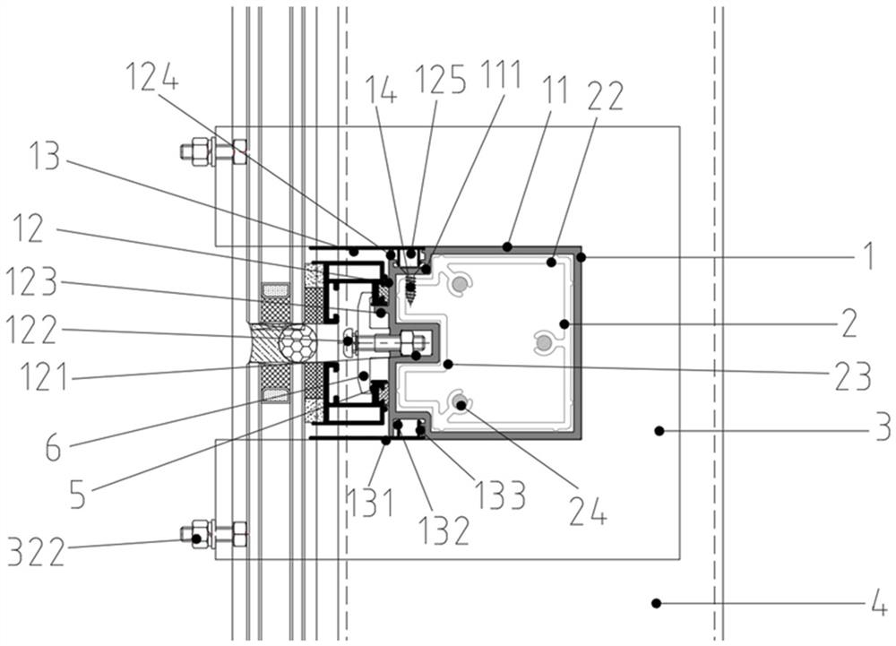
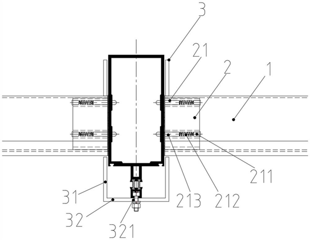
[0030] Such as figure 1 , figure 2 As shown, Embodiment 1 of the present invention provides a hidden frame beam structure, which includes three parts: beam 1 , installation sleeve core 2 and installation cam 3 . The installation sleeve core 2 is provided with a spring pin 21, and the spring pin 21 and the installation sleeve core 2 are preassembled as a whole, and then the installation sleeve core 2 is fixedly installed in the cavity at the end of the beam 1, and is fastened and positioned by the screw 14. The installation profile 3 is first installed at the predetermined position of the column 4, and then the whole crossbeam 1 is pushed horizontally along the gap on the side of the installation profile 3 to complete the installation.
[0031] In this embodiment, the beam 1 is a closed single-cavity structure (in other embodiments, it can also be multi-cavity), and the upper and lower beam side panels 11 are formed with L-shaped, facing the inside of the cavity. The twist o...
Embodiment 2
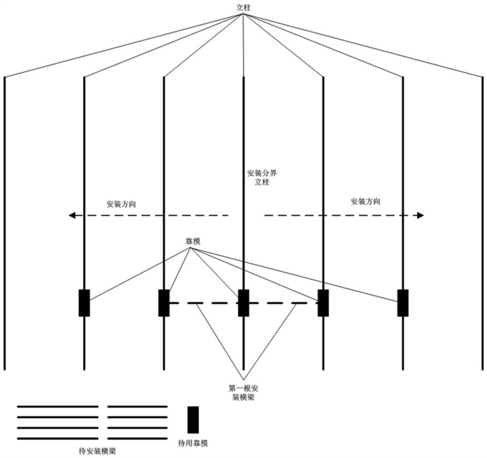
[0038] Please also see image 3 , Embodiment 2 of the present invention provides the method for installing the hidden frame beam described in Embodiment 1, specifically comprising the following steps:
[0039] Step 1: Assemble the installation core 2 and the beam 1 in the factory, cut the beam 1 of the specified specification according to the site installation requirements, pour the spring pins 21 from the end of the installation core 2 into each groove 24 in turn, and confirm the spring pins 21 After the installation is in place, push the installation sleeve core 2 from one end of the beam 1. When the installation sleeve core 2 is just pushed into the cavity of the beam 1, drive a screw 14 into the C-shaped groove 125 of the beam 1, and install the sleeve core 2 Fasten and locate with beam 1;
[0040] Step 2. Complete the processing of the column 4 in the factory, cut the column 4 of specified specifications according to the installation requirements on site, mark the horizo...
PUM
 Abstract
Description
Claims
Application Information
 - R&D
- Intellectual Property
- Life Sciences
- Materials
- Tech Scout
- Unparalleled Data Quality
- Higher Quality Content
- 60% Fewer Hallucinations
Browse by: Latest US Patents, China's latest patents, Technical Efficacy Thesaurus, Application Domain, Technology Topic, Popular Technical Reports.
© 2025 PatSnap. All rights reserved.Legal|Privacy policy|Modern Slavery Act Transparency Statement|Sitemap|About US| Contact US: help@patsnap.com


