Method for verifying on-orbit absolute radiometric calibration result of optical load

An absolute radiometric calibration and calibration technology, applied in the field of remote sensing, can solve the problems of single test target, inconsistent measurement reference, and limited accuracy of ground-based verification, achieve good atmospheric permeability, improve the accuracy of ground-based verification, and eliminate single field Effect of Single Observation Error

Active Publication Date: 2021-05-14
ACAD OF OPTO ELECTRONICS CHINESE ACAD OF SCI +1
View PDF4 Cites 2 Cited by
  • Summary
  • Abstract
  • Description
  • Claims
  • Application Information

AI Technical Summary

Problems solved by technology

Based on this, the demand for high-precision ground-based verification technology for optical load calibration results is aimed at the problems that the current ground-based verification faces a single test target, inconsistent measurement standards, and different test specifications and data processing methods, which lead to serious limitations in the accuracy of ground-based verification. , this patent proposes a multi-test field comprehensive verification method for optical payload on-orbit absolute radiation calibration results. This method will completely innovate the traditional foundation verification mode, minimize the single-field measurement uncertainty in the traditional foundation verification process, and improve Overall verification accuracy and strong practical operability

Method used


Image

  • Method for verifying on-orbit absolute radiometric calibration result of optical load
  • Method for verifying on-orbit absolute radiometric calibration result of optical load
  • Method for verifying on-orbit absolute radiometric calibration result of optical load

Examples


Embodiment Construction

[0032] In order to make the object, technical solution and advantages of the present invention clearer, the present invention will be described in further detail below in conjunction with specific embodiments and with reference to the accompanying drawings.

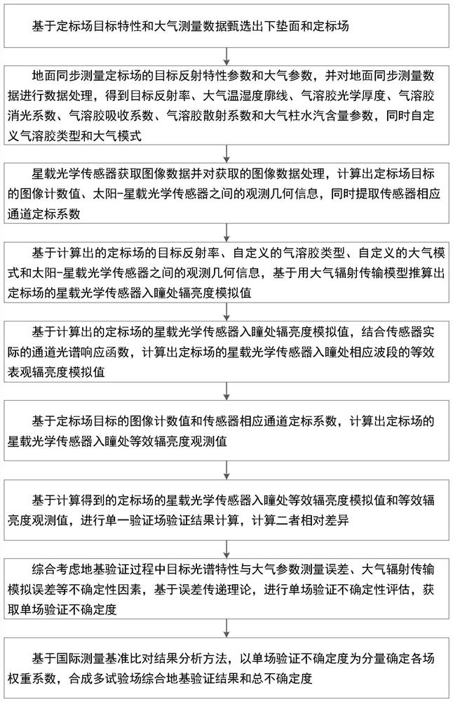
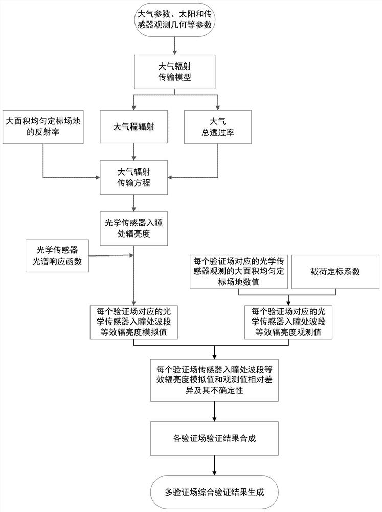
[0033] figure 1 It is a flowchart of a method for verifying the results of on-orbit absolute calibration of optical payloads according to an embodiment of the present invention, figure 2 It is a specific flow chart of the multi-test field comprehensive verification method for the optical load on-orbit absolute radiation calibration result of the embodiment of the present invention. The method includes the following steps:

[0034] Step A: Select the calibration field on the underlying surface based on the target characteristics of the calibration field and the atmospheric measurement data;

[0035]The first step of the multi-test field comprehensive verification method for the on-orbit absolute radiometric calibration r...


PUM


Abstract

The invention discloses a method for verifying an optical load on-orbit absolute radiometric calibration result. The method comprises the following steps: selecting an underlying surface and a calibration field based on calibration field target characteristics and atmospheric measurement data; synchronously measuring target reflection characteristic parameters and atmospheric parameters of the calibration field on the ground, and processing the synchronously measured data on the ground; the method comprises the following steps: acquiring image data based on a satellite-borne optical sensor, processing the image data, and extracting a corresponding channel calibration coefficient of the sensor; calculating a radiance simulation value at the entrance pupil of the satellite-borne optical sensor of the calibration field by using an atmospheric radiation transmission model; calculating the relative difference between the equivalent radiance simulation value and the equivalent radiance observation value at the entrance pupil of the satellite-borne optical sensor of the calibration field; based on the error transfer theory, carrying out single-field verification uncertainty evaluation, and obtaining single-field verification uncertainty; and based on an international measurement basis comparison result analysis method, determining a weight coefficient of each field by taking single-field verification uncertainty as a component, and synthesizing a multi-test-field comprehensive foundation verification result and total uncertainty.

Description

technical field [0001] The invention relates to the technical field of remote sensing, in particular to a method for verifying the on-orbit absolute calibration results of optical loads. Background technique [0002] After the satellite is launched, due to the vibration and changes in the working environment during the launch process, especially the impact of mechanical shock, weightlessness, vacuum, space radiation, etc., as well as the interference of the instrument itself and external factors, the radiation performance of the optical load is often different from the performance of the pre-launch test. There are obvious deviations, and simply using the laboratory calibration results before launch cannot reflect the real radiation performance of the payload during its orbital operation. For example, the United States conducted a ground radiation calibration on the Coastal Zone Color Scanner (CZCS) launched in 1979, and found that the performance of its short-wave part dropp...

Claims


Application Information

Patent Timeline
Patent Type & Authority Applications(China)
IPC IPC(8): G01C25/00G01M11/00
CPCG01C25/00G01M11/00
Inventor 李传荣高彩霞刘耀开马灵玲邱实赵永光唐伶俐王宁钱永刚郑青川
Owner ACAD OF OPTO ELECTRONICS CHINESE ACAD OF SCI
Why Eureka
Try Eureka