Method for testing release flux of multi-component gas on surface of soil body

A technology of gas release and test method, which is applied in the direction of soil material testing and material inspection, and can solve the problems of decreasing concentration gradient, ignoring the diffusion interaction of multi-component gases, and not considering the multi-component mixed gas of landfill gas, etc. , to achieve good reliability

Active Publication Date: 2021-05-14
ZHEJIANG UNIV
View PDF4 Cites 0 Cited by
  • Summary
  • Abstract
  • Description
  • Claims
  • Application Information

AI Technical Summary

Problems solved by technology

However, due to the accumulation of gas concentration on the soil surface due to the placement of the static box, the gas concentration in the static box gradually tends to be saturated, that is, the concentration-time curve C-t curve tends to be nonlinear
At the same time, due to the increase of the concentration on the soil surface, the concentration gradient in the vertical direction decreases, and the flux entering the static cham

Method used


Image

  • Method for testing release flux of multi-component gas on surface of soil body
  • Method for testing release flux of multi-component gas on surface of soil body
  • Method for testing release flux of multi-component gas on surface of soil body

Examples


Embodiment example 1

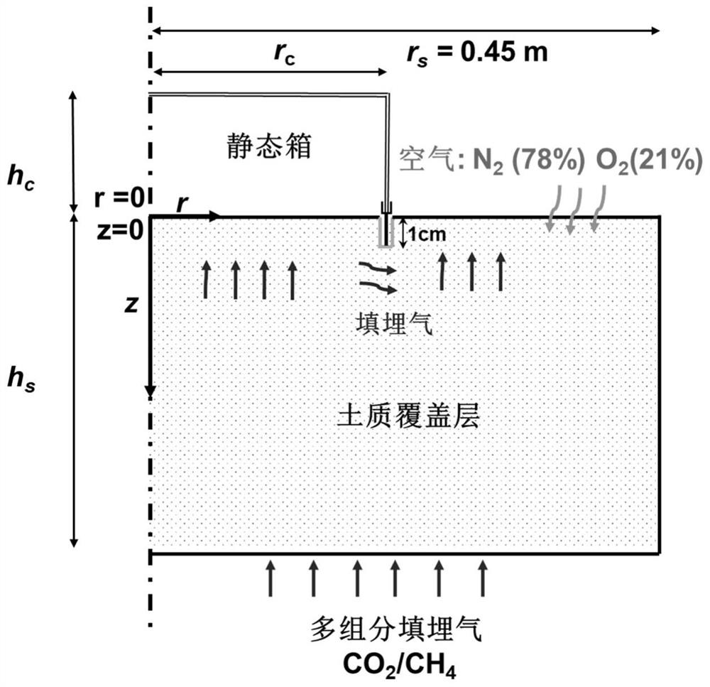
[0070] The present invention is verified by previous experimental data, and the experimental results are from Perera et al. (2002) and Senevirathna et al. (2007) (Figure 4). Perera et al. (2002) conducted a static chamber test in which CO was injected into the bottom of the soil column. 2 199g / m 2 / d, to test CO in static chambers of different sizes 2 concentration. The sizes of static boxes from small to large are: 0.1m×0.05m, 0.2m×0.12m, 0.25m×0.16m (diameter×height). The soil column has a diameter of 0.45m and a height of 0.8m. According to the established multi-component gas migration model, the CO in static boxes of different sizes was simulated after the static box was placed. 2 concentration. The parameter values ​​are shown in Table 1.

[0071] In the static chamber experiment conducted by Senevirathna et al. (2007), the CH passing through the bottom of the soil column 4 and CO 2 The flux is 300g / m 2 / d. The concentration of each component gas in the area whe...

Embodiment example 2

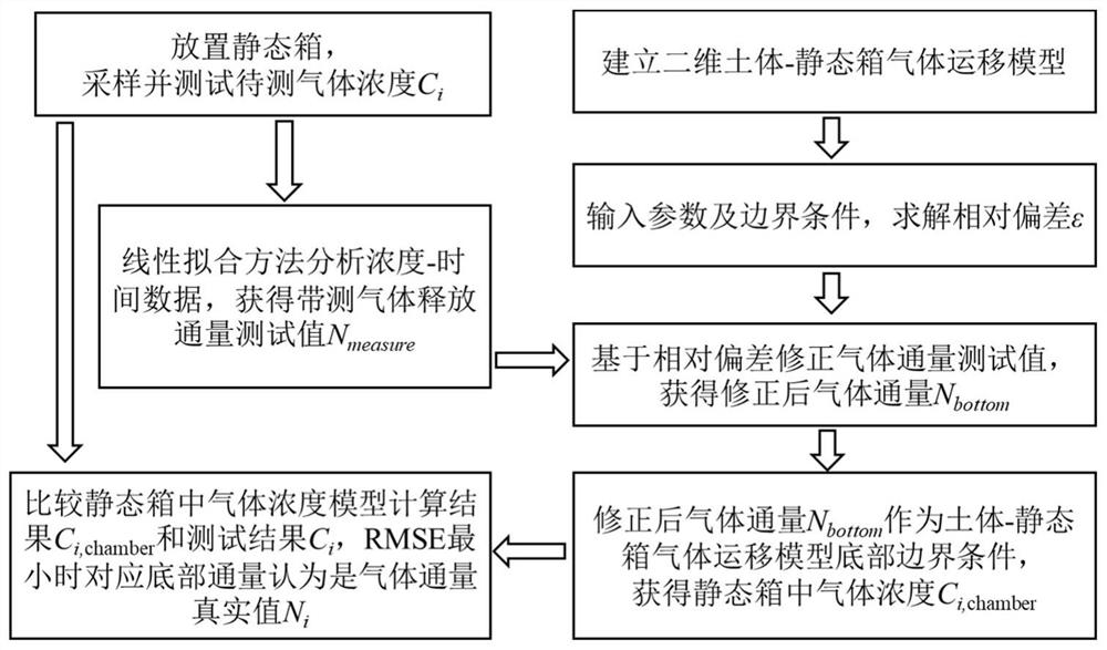
[0081] In this embodiment, a static box with a radius of 0.25m and a height of 0.55m is placed on the surface with loess as the covering layer, and the test corresponds to the CH in the static box at different times. 4 gas concentration. Through the test deviation analysis, assume the test error value and the tortuosity coefficient of gas diffusion. Correct the test flux and input the model to get the CH in the static box 4 concentration.

[0082] Step 1: Randomly select measuring points on the surface of the loess overburden of the landfill, and arrange static boxes. Press the base of the static box into the soil to a certain depth, and add water to seal it. Gas samples were collected at time 0, 15 min and 30 min respectively, and the gas samples were pumped into the Tedlar air bag through the sampling port on the top with a sampling pump. Take the gas bag back to the laboratory, inject 1mL of gas into the GC9800 analyzer with a syringe, and test CH 4 concentration. Eac...


PUM


Abstract

The invention discloses a method for testing release flux of multi-component gas on the surface of a soil body, which is specifically implemented according to the following steps of 1, arranging a static box on the surface of the soil body, sampling and analyzing gas concentration data in the static box, and obtaining a flux test value, 2, establishing a soil body-static box multi-component gas migration numerical model, and acquiring the value range of the test deviation epsilon under different working conditions through calculation, 3, setting a series of epsilon to obtain the corrected gas flux, 4, setting the corrected gas flux as the boundary of the bottom of the model in the step 2, and acquiring the gas concentration in the static box, and 5, selecting the model bottom flux set when the result in the step 4 is closest to the test data in the step 1 as the real release flux. According to the soil surface gas flux testing method provided by the invention, the gas flux testing deviation and the real gas release flux of a static box method considering the top concentration accumulation effect and the multi-component gas interaction can be given.

Description

technical field [0001] The invention relates to a test method for the release flux of multi-component gas on the surface of a soil body, which can determine the test deviation of the gas release flux after considering the interaction of the multi-component gas and the cumulative effect of the concentration on the top of the soil body after placing a static box. The gas release flux obtained by the static box method test can be corrected to obtain the true value of the gas release flux. Background technique [0002] Landfill gas containing various components will be produced after municipal solid waste is degraded in landfill. The composition of landfill gas is complex, the main component is CH 4 (55-60%) and CO 2 (40-45%), also contains traces of malodorous gas (1%). The release of landfill gas has an impact on the atmospheric environment and the lives of surrounding residents. In order to implement relevant measures for landfill gas control, it is first necessary to obta...

Claims


Application Information

Patent Timeline
IPC IPC(8): G01N33/24
CPCG01N33/24
Inventor 左欣茹沈斯亮谢海建陈云敏
Owner ZHEJIANG UNIV
Why Eureka
Try Eureka