Radar shielding blind area calibration method and device

A calibration method and radar blind zone technology, applied in the radar field, can solve the problems of large amount of calculation, slow speed, and inability to meet the calibration of radar blind zone, and achieve the effect of rapid calibration

Pending Publication Date: 2021-05-14
中国人民解放军93114部队
View PDF5 Cites 2 Cited by
  • Summary
  • Abstract
  • Description
  • Claims
  • Application Information

AI Technical Summary

Problems solved by technology

[0003] Conventional radar blind zone calculation uses the same method to calculate each point one by one. The calculation is heavy and the speed is slow, which cannot meet the requirements of rapid radar 360° all-round radar blind zone calibration.

Method used


Image

  • Radar shielding blind area calibration method and device
  • Radar shielding blind area calibration method and device
  • Radar shielding blind area calibration method and device

Examples


Embodiment 1

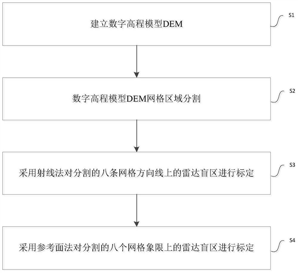
[0048] This embodiment discloses a method for calibrating radar shadowing blind areas, such as figure 1 shown, including the following steps:

[0049] Step S1, based on the digital map information of the radar detection area, establish a digital elevation model DEM based on a regular rectangular grid reference surface; each grid point includes a DEM elevation;

[0050] Specifically, the size of the regular rectangular grid on the reference surface, that is, the width of the grid’s row interval dx and column interval dy, can be determined according to the resolution requirements for the calibration of radar shadowing blind areas. At each grid point (m, n ) includes a DEM elevation information r.

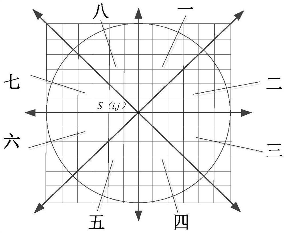
[0051] Step S2. On the grid reference plane, take the grid point S(i, j) where the radar detection point is located as the origin, take the grid with row number i as the horizontal axis, and take the grid with column number j as the vertical axis Axis, according to the eight-quadran...

Embodiment 2

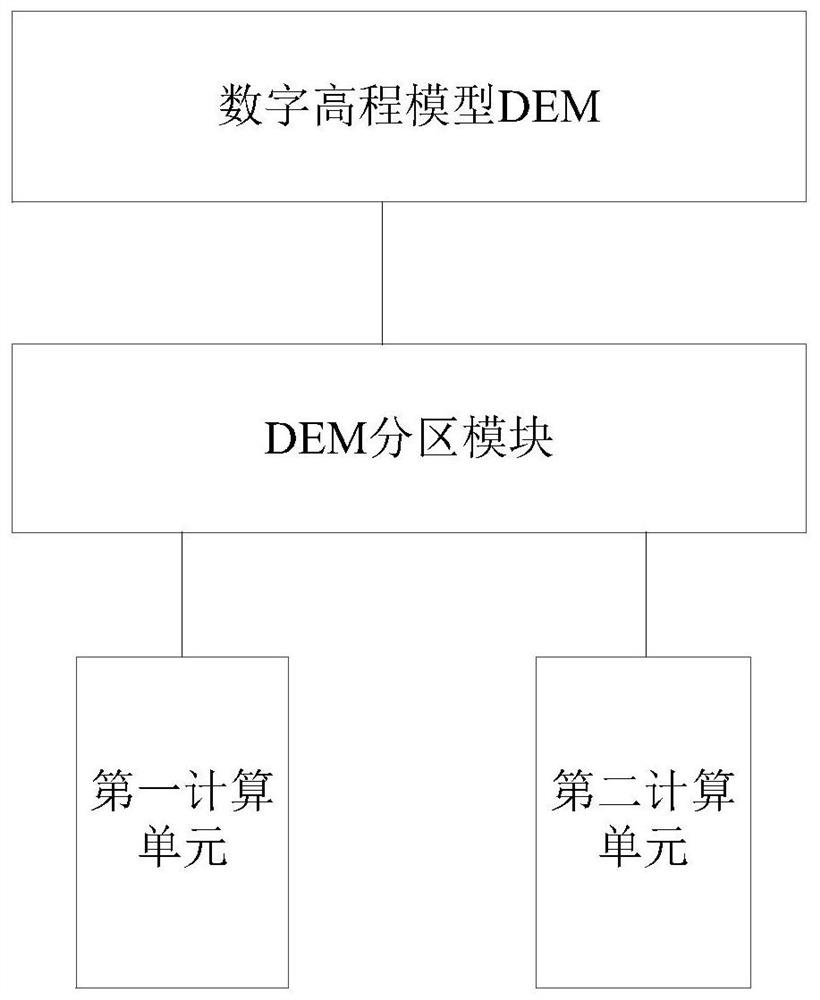
[0094] This embodiment discloses a radar masking blind area calibration device, such as image 3 As shown, it includes digital elevation model DEM, DEM partition module, first calculation unit, second calculation unit,

[0095] Digital elevation model DEM, a digital elevation model DEM based on a regular rectangular grid reference surface; each grid point includes a DEM elevation;

[0096] The DEM partition module is based on the grid point S(i, j) where the radar detection point is located as the origin, the grid with the row number i as the horizontal axis, and the grid with the column number j as the vertical axis, according to the plane Cartesian coordinates The eight-quadrant division method of the system divides the digital elevation model DEM area into eight grid direction lines and eight grid quadrants separated by grid lines;

[0097] The first computing unit is used to obtain eight grid direction line divisions from the DEM division module, and adopts the ray method...


PUM


Abstract

The invention relates to a radar shielding blind area calibration method and device, belongs to the technical field of radars, and solves the calibration problem of radar shielding blind areas, and the method comprises the following steps: on the basis of radar detection area digital map information, establishing a digital elevation model DEM based on a regular rectangular grid reference surface, each grid point comprising a DEM elevation; on a grid reference plane, taking a grid point S (i, j) where the radar detection point is located as an original point, taking a grid with a row number of i as a horizontal axis, taking a grid with a column number of j as a longitudinal axis, and dividing a grid region of the DEM into eight grid direction lines and eight grid quadrants spaced by the adjacent grid direction lines according to an eight-quadrant division mode of a rectangular plane coordinate system; using a ray method to calibrate radar blind areas on the eight grid direction lines; and calibrating the radar blind areas on the eight grid quadrants by adopting a reference plane method. According to the method, parallel computing can be executed by using the multi-core CPU, and rapid calibration of 360-degree radar omnibearing shielding blind areas is realized.

Description

technical field [0001] The invention relates to the technical field of radar, in particular to a method and a device for calibrating radar shadowing blind areas. Background technique [0002] The blind area of ​​radar terrain shadowing is due to the fact that radar waves are blocked by terrain undulating areas during space travel, such as mountains, hills, forests, etc., which have a shielding effect on radar, thus forming that radar waves cannot reach within the effective range (threat radius) space area. The formation of radar terrain shadowing blind zone is only related to the terrain and the position of radar transmitting antenna. [0003] The conventional radar blind zone calculation uses the same method to calculate each point one by one, which requires a large amount of calculation and slow speed, which cannot meet the requirements of rapid radar 360° all-round radar blind zone calibration. Contents of the invention [0004] In view of the above analysis, the pres...

Claims


Application Information

Patent Timeline
Patent Type & Authority Applications(China)
IPC IPC(8): G01S13/89
CPCG01S13/89
Inventor 王日冬张志朱宇涛谭礼晋余博杨丽萍李娜李超
Owner 中国人民解放军93114部队
Why Eureka
Try Eureka