Portable short-focus near-to-eye display system

A near-eye display and short-focus technology, which is applied in optical components, instruments, optics, etc., can solve the problems of being unable to realize lightness and thinness, and the thickness of the near-eye display system is large, so as to shorten the overall thickness, increase the exit pupil distance, and reduce the light intensity. The effect of energy loss

Pending Publication Date: 2021-05-14
GUANGGAN SHANGHAI TECH CO LTD
View PDF0 Cites 5 Cited by
  • Summary
  • Abstract
  • Description
  • Claims
  • Application Information

AI Technical Summary

Problems solved by technology

[0004] In order to solve the problem that the existing display system near-eye display system has a large thickness and cannot be thinned, the present invention provides a light and short-focus near-eye display system

Method used


Image

  • Portable short-focus near-to-eye display system
  • Portable short-focus near-to-eye display system
  • Portable short-focus near-to-eye display system

Examples


Embodiment Construction

[0051] The following will clearly and completely describe the technical solutions in the embodiments of the application with reference to the drawings in the embodiments of the application. Apparently, the described embodiments are only some, not all, embodiments of the application. Based on the embodiments in this application, all other embodiments obtained by persons of ordinary skill in the art without making creative efforts belong to the scope of protection of this application.

[0052] It should be noted that when a component is said to be "connected" to another component, it can be directly connected to the other component or there can also be an intervening component; when a component is said to be "fixed" to another component, it can Can be fixed directly to another component or there can also be a centered component. "Left" is the side facing the pupil position, and "Right" is the side away from the pupil and facing the environment.

[0053] Unless otherwise defined...


PUM


Abstract

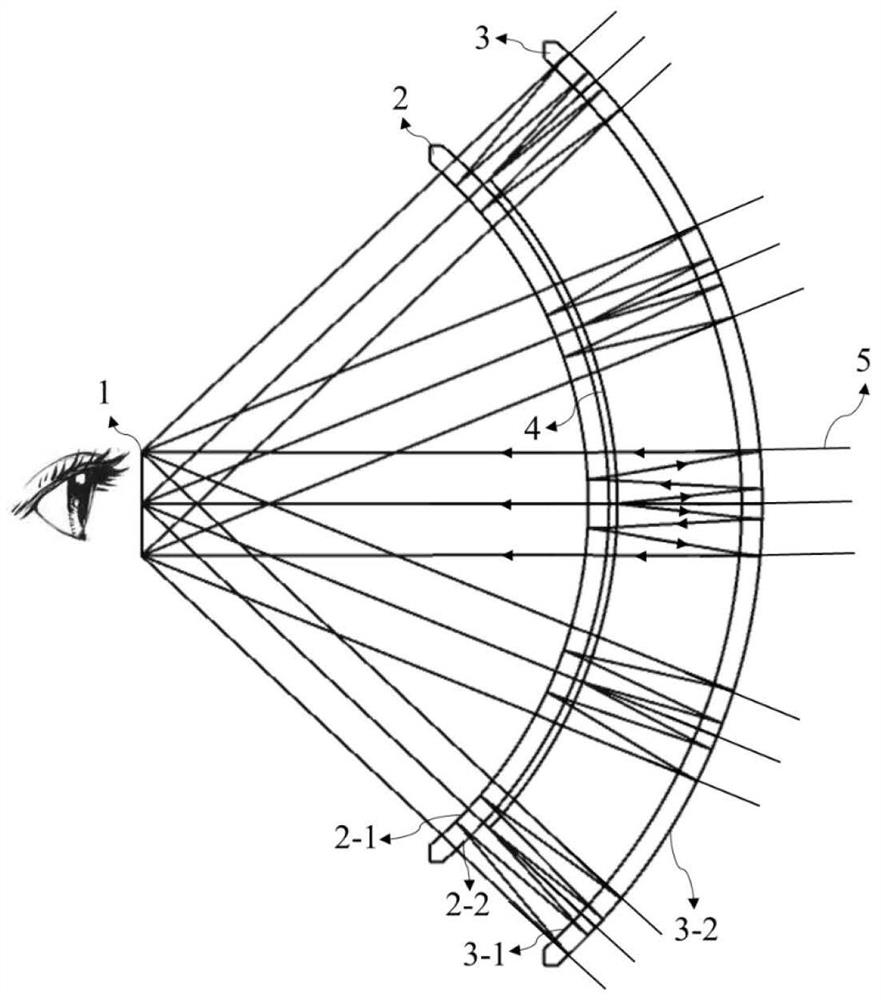
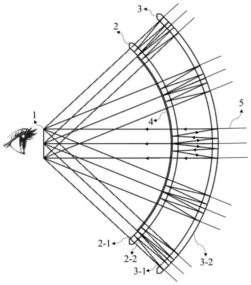
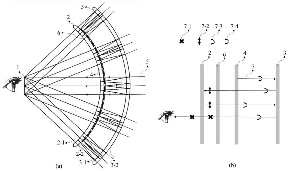
The invention provides a portable short-focus near-to-eye display system, relates to the technical field of near-to-eye display, and solves the problem of contradiction between optical performance and volume in the existing AR technology. The system comprises a micro display, an inner side lens and a concave surface partial reflector; the lenses close to the eye pupil position are inner side lenses, and the lenses far away from the eye pupil position are concave surface partial reflectors; the micro display is a rotary linear display or a transparent display. Through multiple reflections, the light path is folded, so that the distance between the convex surface part reflector and the concave surface part reflector is shortened, the thickness of the glasses can be reduced to the maximum extent, and lightness and thinness are realized.

Description

technical field [0001] The invention relates to the technical field of near-eye display, in particular to a portable short-focus near-eye display system. Background technique [0002] Near-eye display can provide users with a super large 3D image, and at the same time, the displayed image can be integrated with the real environment. It has a very wide range of applications in daily life and industrial fields. [0003] At present, the most promising is optical waveguide AR glasses, which can realize the appearance similar to ordinary glasses, but due to the constraints of refractive index and diffraction efficiency, it is difficult to break through the angle of view, which is generally about 50° diagonally, and its maximum The disadvantage is that the ultra-low energy efficiency will cause the entire system to consume a lot of power. The present invention solves the above problems by using spherical symmetry. Based on the spherical symmetry technology, I have previously appl...

Claims


Application Information

Patent Timeline
Patent Type & Authority Applications(China)
IPC IPC(8): G02B27/01G02B27/28
CPCG02B27/0101G02B27/286
Inventor 杨建明
Owner GUANGGAN SHANGHAI TECH CO LTD
Why Eureka
Try Eureka