Supercharge Your Innovation With Domain-Expert AI Agents!

Chair back screw mounting machine

A technology for installing screws and chair backs, which is applied in the field of chair back installation screw machines, and can solve problems such as easy loosening of bolts, the separation of the chair back board from the chair back, and cumbersome operations

Pending Publication Date: 2021-05-18
ZHEJIANG BAIZHIJIA FURNITURE
View PDF0 Cites 0 Cited by
  • Summary
  • Abstract
  • Description
  • Claims
  • Application Information

AI Technical Summary

Problems solved by technology

[0002] like figure 1 and figure 2 as shown, figure 1 The back of the chair is the existing structure, figure 2 The chair back panel structure is also a relatively common structure at present. At present, in the process of making the chair back, the chair back panel needs to be combined with the chair back to enhance the comfort of the human body's back against the chair back; the traditional chair back The board and the seat back are connected by bolt fastening. The disadvantage of this connection is that on the one hand, the operation is cumbersome and the precision between the screw holes is high; on the other hand, the bolts are easy to loosen during use, resulting in The back of the chair is separated from the back of the chair; some improvements are made through the clamping method, that is, the back of the chair is provided with fasteners similar to petals, and the back of the chair is provided with corresponding fasteners, which are bent and deformed inwards to squeeze into the buckles However, there is a problem in this method, that is, once one petal of the petal fastener is damaged, the stability of the connection between the two will be greatly affected; therefore, the applicant designed a new screw structure, It is used for the fastening of the back panel and the back of the chair; at present, the working method of screwing the screws into the back mounting column of the back of the chair is still relatively traditional. The general process is that the staff first pushes the material from the processed screw Select the screws from the middle, and then manually screw them into the seat back mounting column one by one. biased, making the chair back unusable

Method used


Image

  • Chair back screw mounting machine
  • Chair back screw mounting machine
  • Chair back screw mounting machine

Examples


Embodiment 1

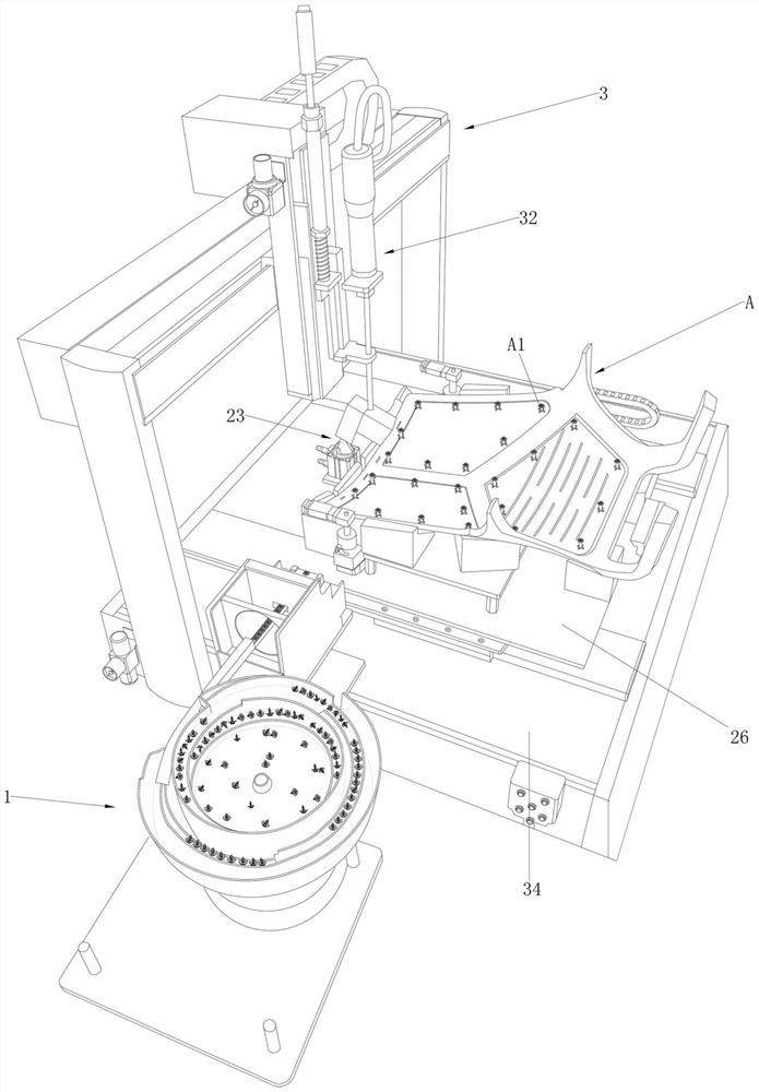
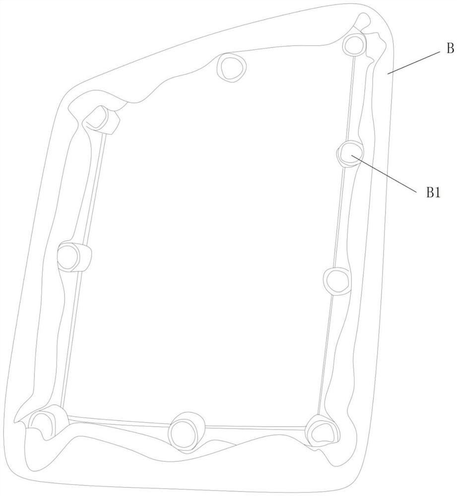
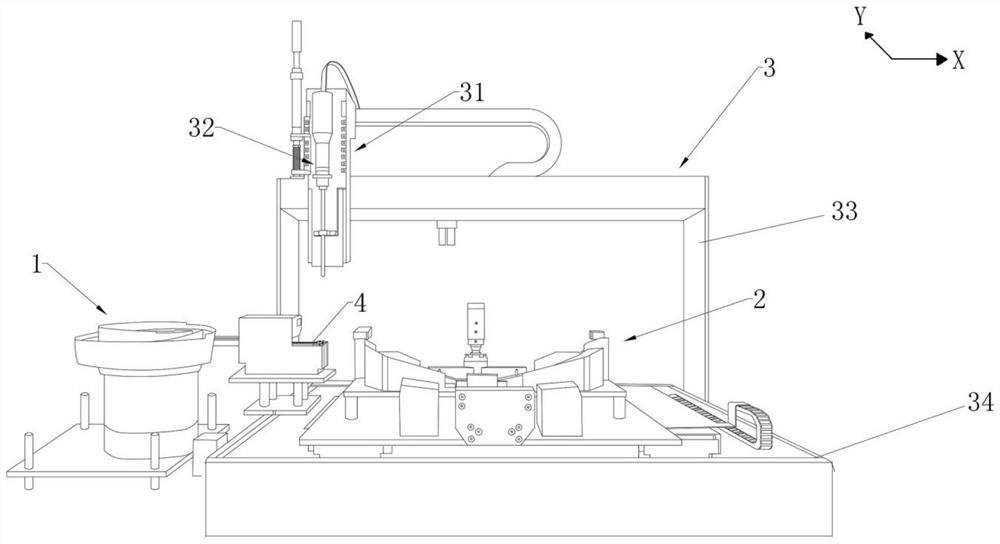
[0032] Referring to Fig. 1 to Fig. 1 of the accompanying drawings of the description of the present invention Figure 9As shown, according to a preferred implementation of the present invention, a screw machine for installing a chair back includes a screw feeding mechanism 1, a chair back clamping and fixing mechanism 2 and a manipulator assembly 3, and the chair back clamping and fixing mechanism 2 is located on the discharge track 13 Adjacent to the end, the manipulator assembly 3 includes a mounting frame and a manipulator 32 arranged on the mounting frame, a lifting arm 31 is slidably arranged on the mounting frame, and the manipulator 32 is disposed on the bottom of the lifting arm 31 , through the back and forth movement of the lifting arm 31 and the up and down driving of the manipulator 32 between the screw feeding mechanism 1 and the chair back clamping and fixing mechanism 2; the manipulator 32 grabs the screw 4 located in the screw feeding mechanism 1 and places it ...


PUM


Abstract

The invention relates to the field of chair manufacturing and machining, in particular to a chair back screw mounting machine. The machine comprises a screw feeding mechanism, a chair back clamping and fixing mechanism and a manipulator assembly, wherein the chair back clamping and fixing mechanism is located at the position adjacent to the tail end of a discharging rail, and a manipulator grabs screws located in the screw feeding mechanism, places the screws on chair back mounting columns located in the chair back clamping and fixing mechanism, and twists and fixes the screws into the chair back mounting columns. A complete mounting assembly line system of screw grabbing, chair back fixing, screw carrying and screw twisting into the chair back mounting columns is realized, the overall working efficiency is improved, and time and labor are saved.

Description

technical field [0001] The invention relates to the field of chair manufacturing and processing, in particular to a chair back mounting screw machine. Background technique [0002] Such as figure 1 and figure 2 as shown, figure 1 The back of the chair is the existing structure, figure 2 The chair back panel structure is also a relatively common structure at present. At present, in the process of making the chair back, the chair back panel needs to be combined with the chair back to enhance the comfort of the human body's back against the chair back; the traditional chair back The board and the seat back are connected by bolt fastening. The disadvantage of this connection is that on the one hand, the operation is cumbersome and the precision between the screw holes is high; on the other hand, the bolts are easy to loosen during use, resulting in The back of the chair is separated from the back of the chair; some improvements are made through the clamping method, that is...

Claims


Application Information

Patent Timeline
IPC IPC(8): B23P19/06
CPCB23P19/06
Inventor 周根富张永永孟祥永
Owner ZHEJIANG BAIZHIJIA FURNITURE
Features
  • R&D
  • Intellectual Property
  • Life Sciences
  • Materials
  • Tech Scout
  • Unparalleled Data Quality
  • Higher Quality Content
  • 60% Fewer Hallucinations
Learn More