

Material bonding device and machining method of neodymium iron boron tile-shaped magnet
A processing method, NdFeB technology, applied in metal processing equipment, manufacturing tools, grinding workpiece supports, etc., can solve the problems of low efficiency, large total grinding amount of arc surface, and affecting the precise processing of multi-wire cutting
- Summary
- Abstract
- Description
- Claims
- Application Information
AI Technical Summary
Problems solved by technology
Method used
Image

Examples
example 1
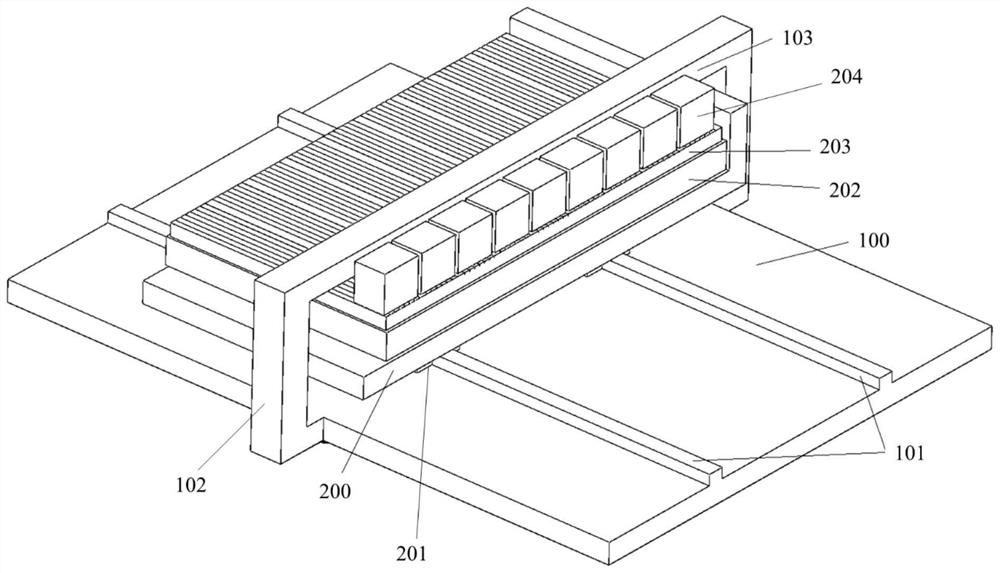
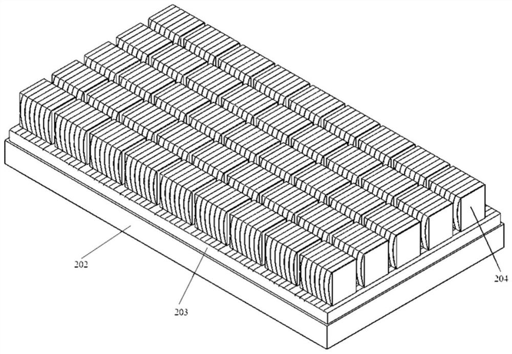
[0041] Step 1: Put the material plate with the backing plate on the multi-wire cutting machine for cutting, the cutting depth is 1~2mm, make the cutting marks on the surface of the backing plate, clean the surface of the material plate and the material plate platform, and then The material board is placed on the material board platform, and the front end of the material board is tightly attached to the front end of the material board platform to ensure that the cutting marks are perpendicular to the sticky tooling rod. The height of the NdFeB magnet blank is the width of the tile. The width of the NdFeB magnet blank is the length of the tile. Based on the sticky tooling bar, the width direction of the NdFeB magnet blank is close to the sticky tooling bar, and the front end surface of the NdFeB magnet blank in the length direction is guaranteed Align with the cutting marks, use adhesive to bond the NdFeB magnet blanks on the backing plate, follow the above method to bond the NdF...
example 2
[0047] Step 1: Put the material plate with the backing plate on the multi-wire cutting machine for cutting, the cutting depth is 1~2mm, make the cutting marks on the surface of the backing plate, clean the surface of the material plate and the material plate platform, and then The material board is placed on the material board platform, and the front end of the material board is tightly attached to the front end of the material board platform to ensure that the cutting marks are perpendicular to the sticky tooling rod. The height of the NdFeB magnet blank is the width of the tile. The width of the NdFeB magnet blank is the length of the tile. Based on the sticky tooling bar, the width direction of the NdFeB magnet blank is close to the sticky tooling bar, and the front end surface of the NdFeB magnet blank in the length direction is guaranteed Align with the cutting marks, use adhesive to bond the NdFeB magnet blanks on the backing plate, follow the above method to bond the NdF...
example 3
[0053] Step 1: Put the material plate with the backing plate on the multi-wire cutting machine for cutting, the cutting depth is 1~2mm, make the cutting marks on the surface of the backing plate, clean the surface of the material plate and the material plate platform, and then The material board is placed on the material board platform, and the front end of the material board is tightly attached to the front end of the material board platform to ensure that the cutting marks are perpendicular to the sticky tooling rod. The height of the NdFeB magnet blank is the width of the tile. The width of the NdFeB magnet blank is the length of the tile. Based on the sticky tooling bar, the width direction of the NdFeB magnet blank is close to the sticky tooling bar, and the front end surface of the NdFeB magnet blank in the length direction is guaranteed Align with the cutting marks, use adhesive to bond the NdFeB magnet blanks on the backing plate, follow the above method to bond the NdF...
PUM
| Property | Measurement | Unit |
|---|---|---|
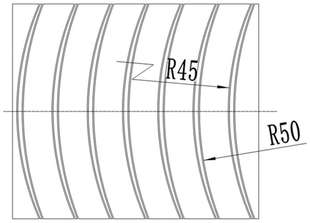
| Radius of outer arc | aaaaa | aaaaa |
| Inner arc radius | aaaaa | aaaaa |
| Wall thickness | aaaaa | aaaaa |
Abstract
Description
Claims
Application Information