
Auxiliary runner structure for preventing deformation of injection product

A technology of injection molding products and auxiliary flow, applied in the field of injection molding process equipment, can solve problems such as affecting the assembly of assembly parts, easy to be damaged, and easy to be distorted and deformed.

Active Publication Date: 2021-05-18
DONGFENG MOTOR CORP HUBEI
View PDF13 Cites 3 Cited by
  • Summary
  • Abstract
  • Description
  • Claims
  • Application Information

AI Technical Summary

Problems solved by technology

[0002] In automobiles, some injection molded parts need to be designed in a partially disconnected state due to the influence of the overall shape. This shape design leads to poor rigidity of the product itself and is prone to distortion and deformation.
The whole process of injection molding process is: mold closing - filling - holding pressure - cooling - mold opening and picking - next cycle, in which the filling process forms 95% - 99% of the product volume, and the rest depends on The product is filled with pressure, and the shrinkage of the product after cooling is compensated by holding the pressure; the product shrinks after cooling, and the product also shrinks and deforms at the disconnection, so the size is unqualified, which in turn affects the assembly of the assembly parts; At the same time, this product also needs to be electroplated after injection molding. Electroplating products have a very important feature. The end and sharp corners of the product are easy to accumulate electroplating solution, and it is easy to be scratched after electroplating. Therefore, when designing general injection molds, it is necessary to End Design Plating Protection Corner

Method used


Image

  • Auxiliary runner structure for preventing deformation of injection product
  • Auxiliary runner structure for preventing deformation of injection product
  • Auxiliary runner structure for preventing deformation of injection product

Examples


Embodiment Construction

[0024]The present invention will be described in detail below with reference to the accompanying drawings and specific examples, which are not particularly defined by the present invention.

[0025]Some of the existing products, the appearance requires high, during the injection molding process, the product is not ideal in the capacity of the mobile terminal, that is, the pressure can not make the plastic to the flow end for suppression. How to solve the contraction deformation of the product in the disconnection, becoming the key to such parts in the injection molding process.

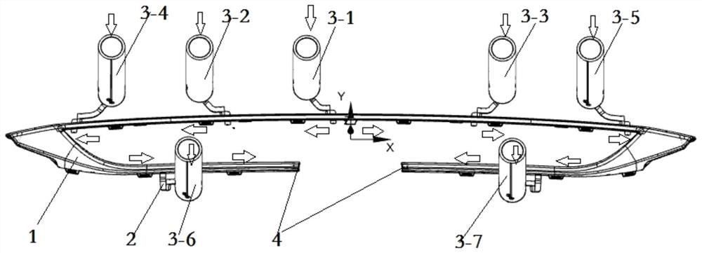
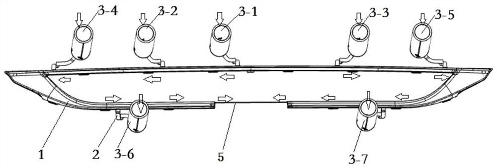
[0026]Such asfigure 1 The products shown in the prior art, the outer surface is the outer surface, the following is a non-external surface, after injection molding, I need to perform electroplating, I is disconnected, the flow end of the product is injection molded, disconnected There are three directions in X, Y, Z. Since the appearance quality requirements are very high, there is no appearance of the appearance...


PUM


Abstract

The invention discloses an auxiliary runner structure for preventing deformation of an injection product. The auxiliary runner structure comprises a mold cavity channel, a main injection nozzle and a plurality of injection nozzles. Plastic melt passes through the mold cavity channel, the main injection nozzle and the injection nozzles communicate with the mold cavity channel through pouring gates, and control valve needles are arranged in the main injection nozzle and the injection nozzles. The auxiliary runner structure is arranged at the broken plastic melt flowing tail end of the mold cavity channel, is connected to the bottom of the product, and comprises a first auxiliary pouring gate, a second auxiliary pouring gate, a third auxiliary pouring gate, a fourth auxiliary pouring gate and a flowing channel. The first auxiliary pouring gate and the third auxiliary pouring gate are located on the same horizontal plane, and the second auxiliary pouring gate is opposite to the first auxiliary pouring gate. The structural strength and rigidity of the injection product before electroplating are improved, and the product cannot be distorted or deformed in the whole electroplating process.

Description

Technical field[0001]The present invention belongs to the technical field of injection molding equipment, and in particular to a auxiliary flow path structure to prevent the deformation of injection molded products.Background technique[0002]In the car, there are some injection molding parts, which are impact on the overall shape, requires a local disconnected state, which results in a poor product itself, and it is easy to generate distortion deformation. The entire process of injection molding process is: Co-mold-filled-pressure-cooling-mold pick-up-next cycle, wherein the process of filling, forming product volume 95% - 99%, the remainder relying on Pressure to achieve the product full, and by pressing pressure to compensate the amount of shrinkage after cooling; the product is contracted after cooling, the product is also contraction deformation in the disconnection, thereby unqualified, and the assembly of the assembly of the assembly; At the same time, this product also needs t...

Claims


Application Information

Patent Timeline
IPC IPC(8): B29C45/27
CPCB29C45/2701B29C45/2708B29C45/2703
Inventor 肖海东张琴王贞赵延强吴阳春
Owner DONGFENG MOTOR CORP HUBEI
Learn More