Core pulling mechanism and elbow plastic processing mold using same

A core-pulling mechanism and a technology for processing molds, which are applied in household appliances, other household appliances, applications, etc.

Pending Publication Date: 2021-05-18
CHANGZHOU INST OF MECHATRONIC TECH
View PDF0 Cites 2 Cited by
  • Summary
  • Abstract
  • Description
  • Claims
  • Application Information

AI Technical Summary

Problems solved by technology

[0005] The second object of the present invention is to provide a bending plastic processing mold to solve the technical problem of improving the use efficiency of the mold

Method used


Image

  • Core pulling mechanism and elbow plastic processing mold using same
  • Core pulling mechanism and elbow plastic processing mold using same
  • Core pulling mechanism and elbow plastic processing mold using same

Examples


Embodiment 1

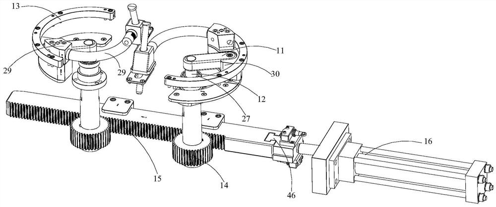
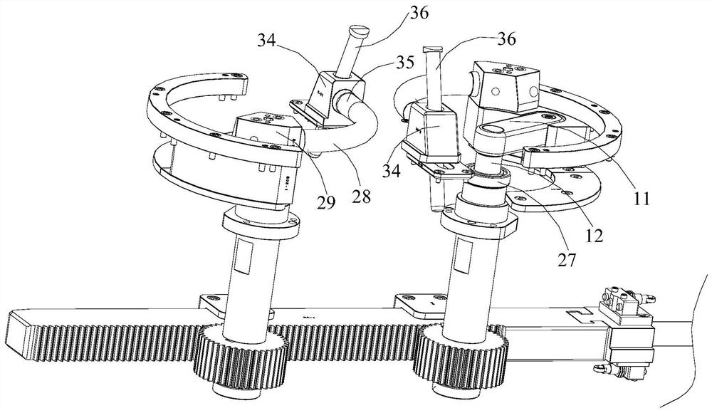
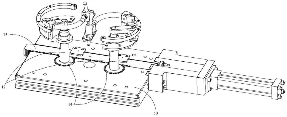
[0048] see Figure 1 to Figure 3 As shown, this embodiment provides a core-pulling mechanism, including: a pair of core-pulling assemblies arranged in mirror images, and a power assembly suitable for simultaneously driving a pair of core-pulling assemblies to run; wherein the core-pulling assembly includes a crank 11, and a crank 11 a rotating central axis 12 connected to one end, an elbow core-pulling connected to the end of the crank 11 away from the rotating central axis 12, and a core-pulling track 13 arranged outside the elbow core-pulling; the core-pulling track 13 used in this embodiment It is an arc structure, and the core-pulling track 13 of this arc structure is set in accordance with the specific shape of the bent pipe product 100, that is, for the bent pipe product 100, it is suitable for the bent pipe built into the bent pipe product 100 The core-pulling head must also be in an arc-shaped structure, so that the core-pulling track 13 with an arc-shaped structure ca...

Embodiment 2

[0051] see Figure 1 to Figure 9As shown, on the basis of the core-pulling mechanism in Embodiment 1, this embodiment provides a bending pipe plastic processing mold, including: a moving mold assembly and a fixed mold assembly used in conjunction, and in the moving mold assembly A core-pulling mechanism is provided; wherein the fixed mold assembly includes a fixed template 21 and a fixed mold kernel 22 arranged in the fixed template 21; the movable mold assembly includes a movable template 23 and a movable mold kernel 25 arranged in the movable template 23; And the fixed mold core 22 and the movable mold core 25 cooperate to form an injection molding cavity 26; the elbow core pulling part of the core pulling mechanism extends into the injection molding cavity 26. Specifically, for the injection molding cavity 26 suitable for forming the elbow product 100, the half structure of the injection molding cavity 26 is respectively provided in the fixed mold core 22 and the movable mo...

Embodiment approach

[0057] In an optional embodiment, a slider shovel base 37 is also provided at the end of the body part 34 of the slider away from the tubular insertion part 35, and the slider shovel base 37 can follow the slider along the inclined guide post 36. Synchronize movement during movement. In this embodiment, the set slider shovel base 37 is used to realize the limitation of the end of the slider away from the elbow core-pulling, so as to ensure the shaping of the elbow product 100 from the end away from the elbow core-pulling during the injection molding process of the product. , so as to effectively ensure the injection molding effect of the elbow product 100 .

[0058] In addition, during the movement of the slider along the inclined guide post 36 , in this embodiment, a slider guide rail 38 is provided on the end faces of the slider on both radial sides corresponding to the tubular insertion portion 35 to limit the movement of the slider. The track, that is, the sliding block i...


PUM


Abstract

The invention discloses a core pulling mechanism and a bent pipe processing mold using the same. The core pulling mechanism comprises a pair of core pulling assemblies arranged in a mirror image mode and a power assembly suitable for driving the pair of core pulling assemblies to operate at the same time, wherein each core pulling assembly comprises a crank, a rotating middle shaft connected with one end of the crank, an elbow loose core connected with one end, far away from the rotating middle shaft, of the crank, a core pulling track arranged on the outer side of the elbow loose core and a driving gear; the elbow loose core is suitable for moving along the core pulling track to be separated from a bent pipe product; the driving gear sleeves the end, far away from the crank, of the rotating middle shaft; and the power assembly is simultaneously connected with the driving gears respectively included in the pair of core pulling assemblies. The use efficiency of the bent pipe processing mold can be effectively improved.

Description

technical field [0001] The invention relates to the technical field of moulds, in particular to a core-pulling mechanism and an elbow plastic processing mold using the core-pulling mechanism. Background technique [0002] During the injection molding process of the plastic elbow, after the injection molding process is completed, it is necessary to use the demoulding technology to realize the operation of separating the injected plastic elbow from the mold. In fact, in the injection molding process of the plastic elbow, the effect of the elbow forming is considered, and the core pulling structure is built in the elbow, and the core pulling structure also needs to be pulled out during the demoulding process of the elbow. Therefore, improving the efficiency of the core-pulling process of the built-in core-pulling structure of the bent pipe will directly affect the efficiency of the overall bent pipe processing. [0003] In addition, in conventional molds for processing plastic...

Claims


Application Information

Patent Timeline
Patent Type & Authority Applications(China)
IPC IPC(8): B29C45/33B29C45/26B29C45/40B29L23/00
CPCB29C45/2602B29C45/261B29C45/332B29C45/401B29L2023/004
Inventor 黄可王永
Owner CHANGZHOU INST OF MECHATRONIC TECH
Why Eureka
Try Eureka