
Concrete compacting machine

A compactor and concrete technology, applied in the field of mechanical equipment, can solve the problems of large force and falling of loose stones, etc.

Pending Publication Date: 2021-05-18
贵州仁怀卯戌贸易有限公司
View PDF0 Cites 1 Cited by
  • Summary
  • Abstract
  • Description
  • Claims
  • Application Information

AI Technical Summary

Problems solved by technology

[0004] Aiming at the deficiencies in the prior art, the object of the present invention is to provide a concrete compactor to solve the problem in the prior art that when the compactor is used to compact the surface of concrete, the surface of the compaction roller often appears Due to the high pressure, the loose stones contained in the concrete are imprinted on the surface of the compaction roller due to the large force, and with the cleaning cooperation of the traditional compactor, the loose stones after being removed will fall. Defects to already compacted concrete surface

Method used


Image

  • Concrete compacting machine
  • Concrete compacting machine
  • Concrete compacting machine

Examples


no. 1 example

[0029] Such as Figure 1-Figure 5 As shown, the invention provides a kind of technical scheme of concrete compactor:

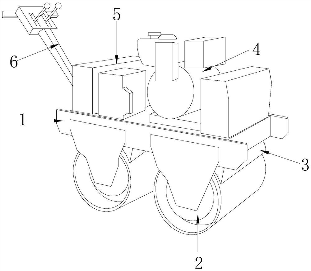
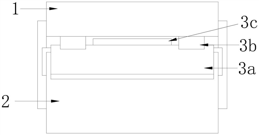
[0030] Such as Figure 1-Figure 2 Shown, a kind of concrete compactor, its structure comprises machine main body 1, compaction shaft 2, straightening device 3, drive motor 4, transmission case 5, pusher 6, and described compaction shaft 2 is provided with two and They are respectively installed on the lower surface of the main body 1. There are two straightening devices 3 which are respectively installed above the compaction shaft 2 and connected to the lower surface of the main body 1. The driving motor 4 is arranged on the main body 1 On the upper surface, the transmission box 5 is electrically connected to the drive motor 4, the push handle 6 is installed on the rear surface of the main body 1 and welded together, and the smoothing device 3 includes a pushing mechanism 3a, a mounting buckle 3b, and a crushing structure 3c , the installation buckle 3b is a...

no. 2 example

[0040] Such as figure 2 , Image 6 As shown, the invention provides a kind of technical scheme of concrete compactor:

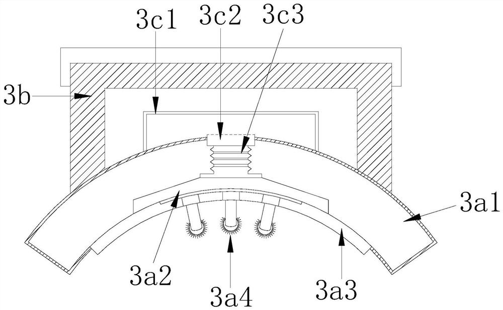
[0041] Such as figure 2 As shown, a concrete compactor, the structure of which includes the nanostructure 3c including a frame 3c1, a single intake valve 3c2, and a connecting pipe 3c3, the single intake valve 3c2 is arranged on the lower surface of the frame 3c1 and is Integrated structure, the connecting pipe 3c3 is arranged on the lower surface of the single air inlet valve 3c2 and connected through it, and the other end of the connecting pipe 3c3 is connected through the perfusion sleeve 3a2, which is beneficial to realize the absorption of stray concrete particles, Therefore, it is avoided that the traditional compactor falls to the compacted concrete surface after the concrete impurities attached to the surface of the compaction shaft are removed.

[0042] Such as Image 6 As shown, the inside of the frame 3c1 is provided with an adsorption airflo...


PUM


Abstract

The invention discloses a concrete compacting machine. The concrete compacting machine structurally comprises a machine main body, a compacting shaft, a smoothing device, a driving motor, a transmission box and a pushing handle. The machine has the beneficial effects that residual concrete on the surface of the compacting shaft is swept and stroked through a pushing and tidying mechanism under the action of a wiping assembly so that the surface of the compacting shaft is ensured to be clean and tidy, meanwhile, restraining strips are matched to be installed in a crossed mode, protruding stones attached to the surface of the compacting shaft in a pressed mode are loosened, a phenomenon that when the compacting shaft attached with stones compacts the surface of concrete, the concrete compaction surface cannot achieve a compact ground holding effect so that the compaction surface is bumpy is prevented, the scattered concrete particles subjected to smoothing are absorbed in a concentrated mode through cooperation of a crushing structure and an overflow opening, and then the situation that when a traditional compacting machine removes concrete impurities attached to the surface of the compacting shaft, redundant concrete falls onto the surface of compacted concrete, and idle work is formed is avoided.

Description

technical field [0001] The invention relates to the field of mechanical equipment, more precisely, it is a concrete compactor. Background technique [0002] In building construction, concrete materials play a very important role. When constructing walls or floors, it is usually necessary to cooperate with a compactor to compact the concrete. [0003] When using a compactor to compact the surface of concrete, it often occurs that the surface of the compaction roller is under high pressure, causing the loose stones contained in the concrete to be printed on the compaction roller due to the large force. The surface of the shaft, and with the removal cooperation of the traditional compactor, the loose stones that have been removed will fall to the concrete surface that has been compacted. Contents of the invention [0004] Aiming at the deficiencies in the prior art, the object of the present invention is to provide a concrete compactor to solve the problem in the prior art t...

Claims


Application Information

Patent Timeline
Patent Type & Authority Applications(China)
IPC IPC(8): E01C19/23
CPCE01C19/236E01C19/238
Inventor 李明亮
Owner 贵州仁怀卯戌贸易有限公司
Learn More