Tunnel wall cleaning vehicle

A technology for cleaning vehicles and tunnel walls, which can be applied to road surface cleaning, cleaning methods, construction, etc., and can solve problems that cannot be used to clean electrical equipment installation areas

Pending Publication Date: 2021-05-18
CRCC HIGH TECH EQUIP CORP LTD
View PDF1 Cites 0 Cited by
  • Summary
  • Abstract
  • Description
  • Claims
  • Application Information

AI Technical Summary

Problems solved by technology

[0005] In order to solve the above-mentioned technical defects existing in the prior art, the object of the present invention is to provide a tunnel wall cleaning vehicle, which adopts the dry ice cleaning method and can carry out online cleaning of the railway tunnel w

Method used


Image

  • Tunnel wall cleaning vehicle
  • Tunnel wall cleaning vehicle
  • Tunnel wall cleaning vehicle

Examples


Embodiment 1

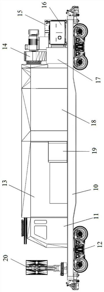
[0044] Such as figure 1 Shown, according to the structural representation of the tunnel wall cleaning vehicle of the present invention. The tunnel wall cleaning vehicle of the present invention comprises a car body 10, and bogies 12 are respectively arranged on the front and rear sides below the car body 10, and the two sets of bogies 12 on the front and rear sides can be the same or can be selected differently according to needs. The bogies 12 are The running system of the whole vehicle is representative; the top of the car body 10 is provided with a driver's cab 11, a power room 13, a fan 14, an air compressor 15, a hydraulic system 16 and an electrical system 17, and the cleaning vehicle is also provided with a dust removal system 18 and dry ice cleaning. The working device 20 ; the power room 13 is provided with power equipment required for vehicle work, and a dry ice cleaning device 19 is also provided.

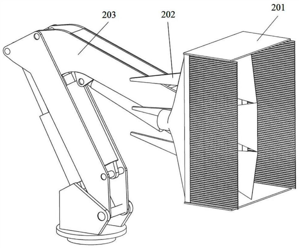
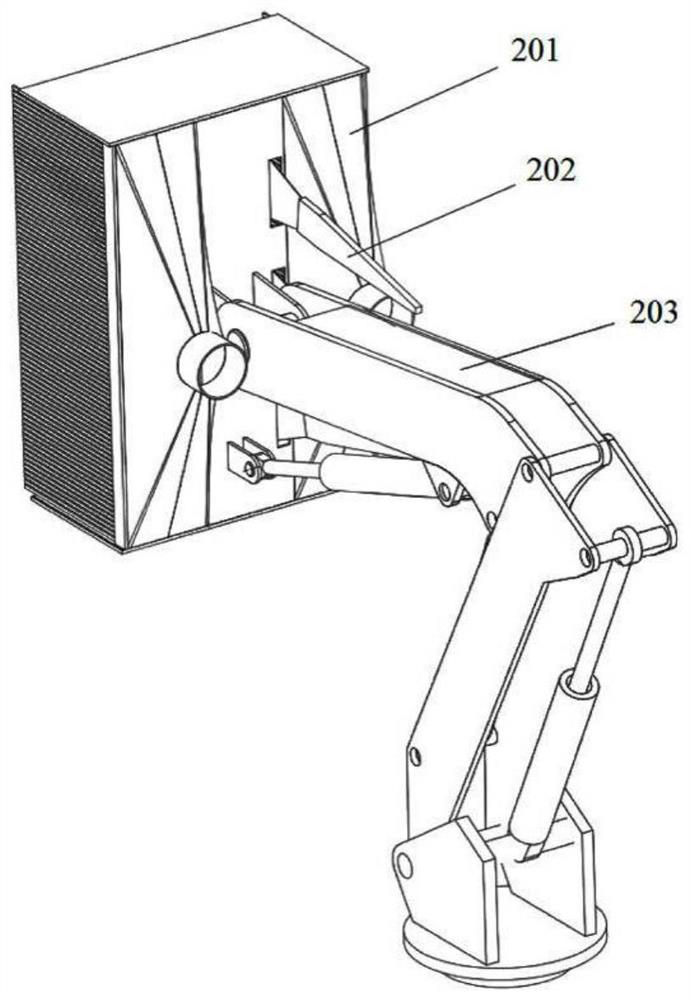
[0045] see next figure 2 , image 3 Shown, according to the tun...

Embodiment 2

[0068] see next Figure 6 , Figure 7 Shown is a schematic structural view of the second embodiment of the tunnel wall cleaning vehicle according to the present invention.

[0069] On the basis of the first embodiment, the second implementation further includes two sliding plates 37 installed on the left and right sides of the cover body 201 and outside the brush discharge plate 32 ; it also includes an adjustment cylinder 204 connected with the sliding plates 37 . A guiding mechanism is provided between the sliding plate 37 and the baffle plate 31 to enable the sliding plate 37 to move back and forth along the bristle length direction of the brush removal plate 32 .

[0070] In this embodiment, guide grooves 311 are provided on the left and right side edges of the baffle plate 31 opposite to the brush discharge plate 32, and rollers 312 are installed in the guide grooves 311, and the sliding plate 37 can be adjusted between the oil cylinder 204 and the rollers 312 Under the...

Embodiment 3

[0076] last read Figure 8 , Figure 9 Shown is a schematic structural view of the third embodiment of the tunnel wall cleaning vehicle according to the present invention.

[0077] This embodiment can be based on any structure of the tunnel cleaning vehicle provided in Embodiment 1 and Embodiment 2, and the tunnel cleaning vehicle can also include: an air knife 205 installed on the back plate 34 of the cover body 201 , the gas input end of the air knife 205 is connected with the high-pressure gas outlet of the air compressor 15 through a pipeline.

[0078] The tunnel cleaning vehicle provided in this embodiment has two cleaning methods: dry ice and air knife blowing. Considering that if dry ice cleaning is used throughout the operation, the amount of carbon dioxide emissions may be relatively large. Therefore, it can be controlled to use dry ice cleaning working device 20 to spray dry ice to clean the tunnel wall in places where local dirt is relatively serious, and wind can...


PUM


Abstract

The invention relates to a tunnel wall cleaning vehicle which comprises a vehicle body (10), bogies (12) are arranged on the front side and the rear side of the lower portion of the vehicle body (10) respectively, the two bogies (12) on the front side and the rear side can be the same or can be different according to needs, and the bogies (12) serve as representatives of a walking system of the whole vehicle. A cab (11), a power room (13), a fan (14), an air compressor (15), a hydraulic system (16) and an electrical system (17) are arranged above the vehicle body (10), and the cleaning vehicle is further provided with a dust removal system (18) and a dry ice cleaning working device (20). The power room (13) is internally provided with power equipment needed by vehicle work and further provided with dry ice cleaning equipment (19). According to the tunnel wall cleaning vehicle, a dry ice cleaning mode is adopted, the tunnel wall cleaning vehicle can carry out on-line cleaning on the railway tunnel wall with power, the tunnel wall cleaning vehicle is particularly suitable for cleaning an electrical equipment installation area on the subway tunnel wall, and the problem that in the prior art, a water washing mode cannot be used for cleaning the electrical equipment installation area is solved.

Description

technical field [0001] The invention relates to the technical field of railway maintenance machinery, in particular to a tunnel wall cleaning vehicle. Background technique [0002] After the construction of the subway tunnel is completed, as the operation time increases, dust pollution and dust accumulation will occur to varying degrees on the top, sides, track bed and trackside equipment of the tunnel wall. In particular, due to the complex structure of the tunnel side walls, cables and equipment, the lack of cleaning and dust accumulation is becoming more and more serious. Long-term accumulation of dust will lead to failure of electrical equipment, such as local short circuit, leakage, and various failures caused by poor heat dissipation of heating elements. Since the dust on the tunnel wall and electrical equipment is very harmful to the safe operation of electrical equipment, the subway tunnel wall, especially the parts where electrical equipment and protruding cable ra...

Claims


Application Information

Patent Timeline
IPC IPC(8): E01H1/08
CPCE01H1/0809E01H1/0836E01H1/0845
Inventor 卫明赵强
Owner CRCC HIGH TECH EQUIP CORP LTD
Why Eureka
Try Eureka