Method for cleaning silt in water inlet pool on front side of water delivery pump station

A cleaning method and technology for water inlet pools, applied in pumping stations, chemical instruments and methods, water supply devices, etc., can solve water pump impeller wear, water quality pollution in pumping stations, and provisions for cleaning sediment in water inlet pools for pumping stations without water delivery, etc. question

Active Publication Date: 2021-05-18
河南省水利勘测设计研究有限公司
View PDF7 Cites 0 Cited by
  • Summary
  • Abstract
  • Description
  • Claims
  • Application Information

AI Technical Summary

Problems solved by technology

[0004] 2. With the operation of the pump station, after the silt in the inlet pool reaches a certain level, the sedimentation speed will no longer be the same as that in the initial operation of the inlet pool, and the sedimentation speed will slow down accordingly, and the sediment brought by the water body will Most of it enters the water pump and pumps it into the water delivery pipeline, and then deposits in the water delivery pipeline; in addition, the machine sediment for the water pump will also accelerate the wear of the pump impeller
[0005] 3. It needs to be cleaned once a year to clean up the silt in the inlet pool. The pump needs to stop running and the water supply should be interrupted to clean up t

Method used


Image

  • Method for cleaning silt in water inlet pool on front side of water delivery pump station
  • Method for cleaning silt in water inlet pool on front side of water delivery pump station
  • Method for cleaning silt in water inlet pool on front side of water delivery pump station

Examples


Embodiment Construction

[0029] The embodiments of the present invention will be described in detail below in conjunction with the accompanying drawings. This embodiment is implemented on the premise of the technical solution of the present invention, and detailed implementation methods and specific operating procedures are provided, but the scope of protection of the present invention is not limited to the following Described embodiment.

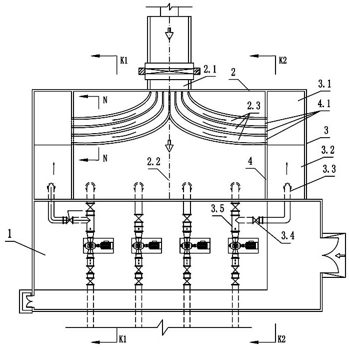
[0030] like Figure 1-4 As shown, the method for cleaning the sediment in the front inlet pool of the water pumping station of the present invention comprises the following steps:

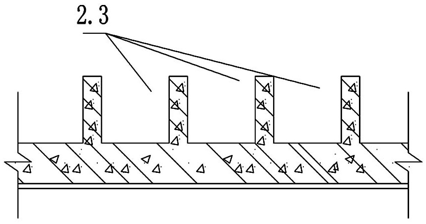
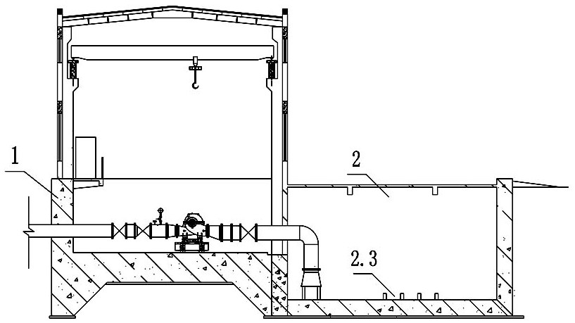
[0031] S1, during the construction period of the water pumping station 1, the water inlet pool 2 is built at the same time, the water inlet 2.1 of the water inlet pool 2 is facing the water pumping station 1, and a water inlet 2.2 is symmetrically arranged on both sides of the water inlet pool 2. The sedimentation ponds 3 with the same structure, two sedimentation ponds 3 are separated...


PUM


Abstract

The invention discloses a method for cleaning silt in a water inlet pool on the front side of a water delivery pump station. The method comprises the following steps of: S1, enabling a water inlet of the water inlet pool to be opposite to the water delivery pump station, and arranging sedimentation tanks on two sides of the water inlet pool respectively, wherein the sedimentation tanks are separated from the water inlet pool through water retaining walls, each sedimentation tank consists of a silt sedimentation area and a water diversion transition area, and a bottom plate of the silt sedimentation area is lower than bottom plates of the water diversion transition area and the water inlet pool; S2, forming a silt guide groove in the bottom plate of the water inlet pool, wherein the silt guide groove extends to the silt sedimentation area from the water inlet; S3, arranging a bypass water diversion pipe in the water diversion transition area, wherein the bypass water diversion pipe communicates with a water pumping pipe of the water delivery pump station through an electric valve; S4, when the water delivery pump station normally runs, forming a water level difference between the water inlet pool and the silt sedimentation area through the combined action of a flow guide hole formed in the water retaining wall and the silt guide groove, and conveying the silt in the water inlet pool to the silt sedimentation area; and S5, periodically cleaning the silt in the silt sedimentation area by adopting a slurry pump truck in a centralized manner. According to the method, the water delivery pump station does not stop during silt cleaning, and normal water supply is guaranteed.

Description

technical field [0001] The invention relates to the field of long-distance water diversion projects of water conveyance channels, in particular to a method for cleaning the sediment in the water inlet pool at the front of a water conveyance pump station. Background technique [0002] In the long-distance water diversion project of large rivers and canals, it is essential to set up water pumping stations, which provide water supply security for urban economic and social sustainable development. The water delivery pump station usually includes: forebay, overhaul gate, water inlet pool, water pump room and auxiliary workshop and other buildings. After the water delivery pump station is put into operation, the staff need to regularly enter the water intake pool to clean up the silted sand, and the water pump needs to be shut down to interrupt the water supply when cleaning the sand. At present, the staff of the water pumping station encounter problems that need to be solved dur...

Claims


Application Information

Patent Timeline
IPC IPC(8): E03B5/00E03B5/02E03F5/10E03F5/14
CPCE03B5/00E03B5/025E03F5/10E03F5/14E03F5/108Y02E10/20
Inventor 耿昕张亚辉吴振宇王爱萍刘润泽王浩张建明王卓然张艺杨晓龙陈方旎闫观清翟冬彬
Owner 河南省水利勘测设计研究有限公司
Why Eureka
Try Eureka