Cast-in-place floor slab quality control device and construction method thereof

A technology for control devices and cast-in-place floor slabs, which is applied in construction, building structure, and processing of building materials, etc., and can solve problems that affect project quality and slab surface leakage

Pending Publication Date: 2021-05-18
中建新疆建工集团第五建筑工程有限公司
View PDF0 Cites 0 Cited by
  • Summary
  • Abstract
  • Description
  • Claims
  • Application Information

AI Technical Summary

Problems solved by technology

The cast-in-place floor slab has the advantages of integrity, high rigidity, and good crack resistance. However, the steel bars of the cast-in-place floor slab are displaced due to workers’ stepping on them before the ...

Method used


Image

  • Cast-in-place floor slab quality control device and construction method thereof

Examples


Embodiment 1

[0029] The cast-in-place floor slab quality control device in this embodiment can be used to fix the negative reinforcement bend anchor section of the floor slab support, and can also be used to control the thickness of the floor slab.

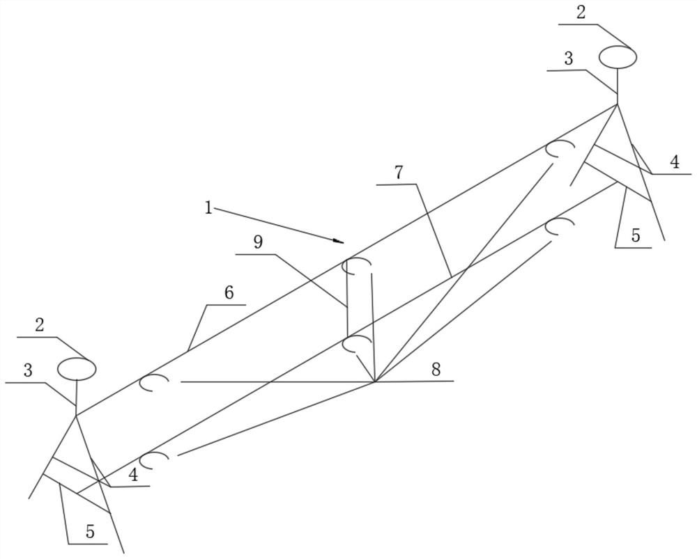
[0030] Specifically, such as figure 1 As shown, the cast-in-place floor quality control device 1 of the present embodiment includes a floor thickness console seat 2, a connecting vertical bar 3, a support oblique bar 4, a support cross bar 5, an upper cross bar 6, a lower cross bar 7, and a floor support support. Rib fixing ring 8 and support vertical bar 9.

[0031] Wherein, the tops of the two support slanting bars 4 are connected together at a predetermined angle, and the middle and lower parts of the two support slanting bars 4 are provided with a support cross bar 5 to form a base frame for installing other components.

[0032] The two ends of the upper cross bar 6 are respectively fixedly installed on the tops of the base frames on both...

Embodiment 2

[0044] The difference between the cast-in-place slab quality control device of the present embodiment and embodiment 1 is:

[0045] The floor thickness control seat and the connecting vertical rod are omitted, the structure is simplified, and the fixing of the negative reinforcement bending anchor section of the floor support is realized, which meets the needs of different application occasions.

[0046] Other structures can refer to Embodiment 1.

Embodiment 3

[0048] The difference between the cast-in-place slab quality control device of the present embodiment and embodiment 1 is:

[0049] Omit the connecting vertical bar, simplify the structure, that is, the floor thickness control seat is directly fixed on the top of the base frame, changing the height of the base frame, can also realize the fixing of the negative reinforcement bending anchor section of the floor support and the control of the floor thickness to meet different applications The needs of the occasion.

[0050] Other structures can refer to Embodiment 1.


PUM

PropertyMeasurementUnit
Thicknessaaaaaaaaaa

Abstract

The invention relates to the technical field of building construction, and particularly relates to a cast-in-place floor slab quality control device. The cast-in-place floor slab quality control device comprises two base frames, an upper cross rod and a lower cross rod, wherein the upper cross rod and the lower cross rod are installed between the two base frames, are parallel to each other and are located on the same vertical plane; and the upper cross rod and the lower cross rod are provided with an upper floor slab support negative rib fixing ring and a lower floor slab support negative rib fixing ring which correspond to each other respectively, and the upper floor slab support negative rib fixing ring and the lower floor slab support negative rib fixing ring are used for fixing floor slab support negative ribs. The cast-in-place floor slab quality control device can be used for fixing floor slab support negative rib bent anchor sections, is easy to produce and install, convenient to operate on site and flexible in arrangement, has the advantages of being high in working efficiency, easy and convenient to operate and convenient to manufacture, is high in practicability and beneficial to popularization, and can effectively reduce displacement of the floor slab support negative rib bent anchor sections due to treading, thereby ensuring the construction quality while ensuring the structural strength requirement of a floor slab.

Description

technical field [0001] The invention relates to the technical field of building construction, in particular to a quality control device for a cast-in-place floor slab and a construction method thereof. Background technique [0002] With the rapid development of economic construction, the standardization of building construction is becoming stronger and stronger, and the requirements for construction quality are getting higher and higher. The control of the quality of steel bar binding and the thickness of the slab for the concealed engineering of the cast-in-place slab is becoming more and more strict. The cast-in-place floor slab has the advantages of integrity, high rigidity, and good crack resistance. However, the steel bars of the cast-in-place floor slab are displaced due to workers’ stepping on them before the concrete is poured, especially before the negative reinforcement of the support is poured. Adjustment will reduce work efficiency, and may cause missing ribs on...

Claims


Application Information

Patent Timeline
IPC IPC(8): E04G21/10E04G21/24
CPCE04G21/10E04G21/24
Inventor 陈亚丽辛化文陈龙肖开怀李垚杨豪豪董正位
Owner 中建新疆建工集团第五建筑工程有限公司
Why Eureka
Try Eureka