Low-pollution combustion head structure

A combustion head, low-polluting technology, applied in burners, combustion types, combustion methods, etc., can solve problems such as energy waste, high pollution emissions, and long fuel retention time

Active Publication Date: 2021-05-18
北京环科环保技术有限公司
View PDF7 Cites 0 Cited by
  • Summary
  • Abstract
  • Description
  • Claims
  • Application Information

AI Technical Summary

Problems solved by technology

[0003] Fuel and air can be mixed inside the mixing chamber and then pass through the flame nozzle into the interior of the furnace, and continue to entrain the air inside the furnace to complete the combustion process. When the burner is in excess of gas or air, there is fuel in the furnace Long residence time, resulting in high pollution emissions, resulting in environmental pollution and energy waste

Method used


Image

  • Low-pollution combustion head structure
  • Low-pollution combustion head structure
  • Low-pollution combustion head structure

Examples


Embodiment 1

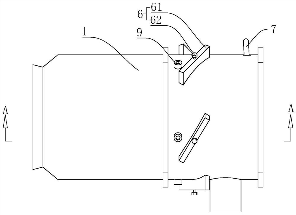
[0039] combine figure 1 and figure 2 , is a low-pollution combustion head structure disclosed in the present application, including a combustion head body 1, the combustion head body 1 is provided with an air inlet 11 and a mixture gas outlet 12, and the air inlet 11 and the mixture gas outlet 12 are respectively arranged on the combustion head On both sides in the length direction of the main body 1 , the air inlet 11 and the mixed gas outlet 12 are oppositely arranged.

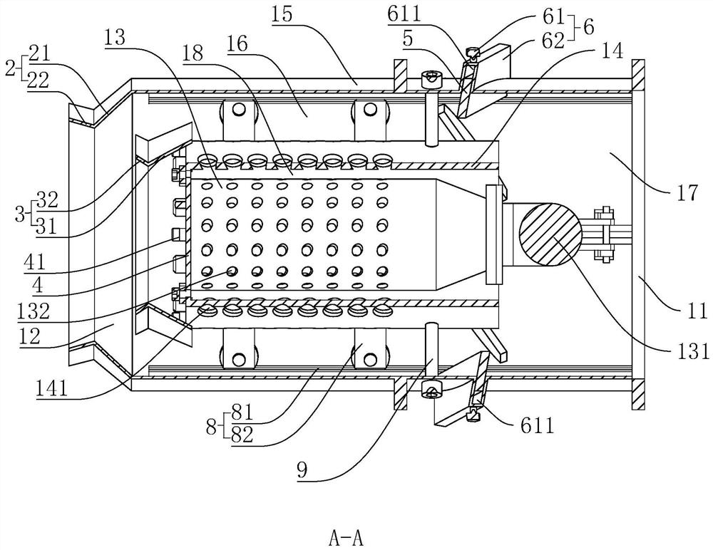
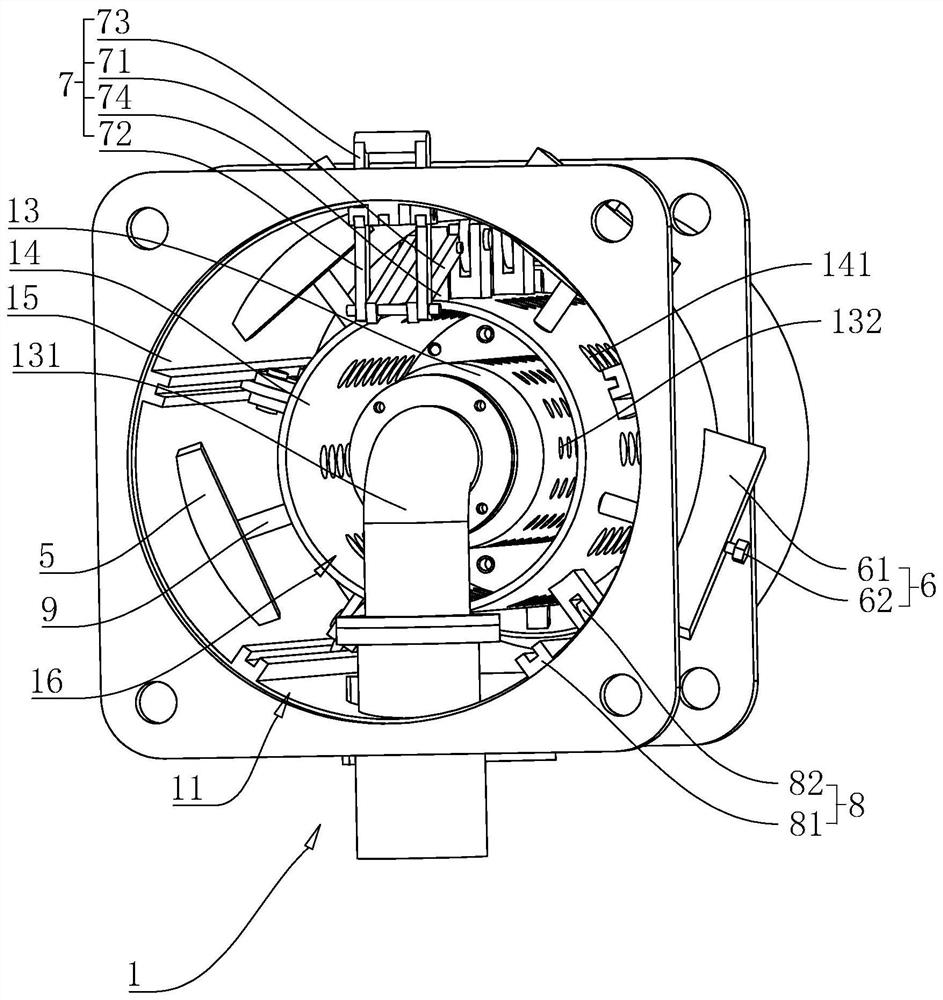
[0040] combine figure 2 and image 3 , the combustion head body 1 includes a gas pipe 13, a primary premixing pipe 14, and a secondary premixing pipe 15 arranged sequentially from the inside and outside, and the gas pipe 13, the primary premixing pipe 14, and the secondary premixing pipe 15 are all cylindrical The axis of the primary premixing pipe 14, the axis of the secondary premixing pipe 15, and the axis of the gas pipe 13 coincide.

[0041] combine figure 2 and image 3 , one end of the second...

Embodiment 2

[0061] The difference between Embodiment 2 and Embodiment 1 is that the combination Figure 4 and Figure 5 , the adjusting blade 5 is arranged in a rectangular shape, the width of the adjusting blade 5 is equal to the distance between the inner wall of the secondary premixing pipe 15 and the outer wall of the primary premixing pipe 14, and a rotating rod is fixed between the adjusting blade 5 and the secondary premixing pipe 15 10. The rotating rod 10 is fixed in the middle of the adjusting blade 5. The secondary premixing pipe 15 is correspondingly provided with a through hole for the rotating rod 10 to pass through. The rotating rod 10 is partly located inside the secondary premixing pipe 15 and partly located on the Outside the secondary premixing pipe 15, the rotating rod 10 is rotatably connected to the secondary premixing pipe 15. Turn the rotating rod 10, and the rotating rod 10 drives the adjusting blade 5 to rotate synchronously. When the adjusting blade 5 rotates u...


PUM


Abstract

The invention relates to a low-pollution combustion head structure, and belongs to the technical field of combustors. For the problems of high pollution emission, environmental pollution and energy waste caused by long residence time of fuel in a hearth, the following technical scheme is provided; the low-pollution combustion head structure is technically characterized in that the low-pollution combustion head structure comprises a combustion head body; the combustion head body is provided with an air inlet and a mixed gas spraying opening and comprises a gas pipe, a primary premixing pipe and a secondary premixing pipe which are sequentially arranged from inside to outside, a primary premixing cavity is defined by the inner wall of the primary premixing pipe and the outer wall of the gas pipe, the gas pipe is provided with a gas nozzle, and a secondary premixing cavity is defined by the secondary premixing pipe and the primary premixing pipe. A premixed gas nozzle is arranged on the primary premixing pipe, the primary premixing cavity and the secondary premixing cavity both communicate with the air inlet, and the secondary premixing cavity communicates with the mixed gas spraying opening. The low-pollution combustion head structure has the advantages that the mixing degree of fuel and air is enhanced, the premixing uniformity of a combustion head is improved, the retention time of the fuel is shortened, and pollutant emission is reduced.

Description

technical field [0001] The present application relates to the technical field of burners, in particular to a low-pollution combustion head structure. Background technique [0002] The burner is a thermal energy device that sends fuel and air into the furnace according to the required concentration, speed, turbulence and mixing method, and enables the fuel to ignite and burn stably in the furnace. The burner includes a swirl generator and a downstream mixing tube. The combustion head has a pilot burner system for maintaining the main flame. The pilot burner system includes a mixing chamber for mixing pilot fuel and auxiliary air. [0003] Fuel and air can be mixed inside the mixing chamber and then pass through the flame nozzle into the interior of the furnace, and continue to entrain the air inside the furnace to complete the combustion process. When the burner is in excess of gas or air, there is fuel in the furnace Long residence time leads to higher pollution discharge...

Claims


Application Information

Patent Timeline
Patent Type & Authority Applications(China)
IPC IPC(8): F23D14/02F23D14/62F23D14/60F23D14/58F23D14/46
CPCF23D14/02F23D14/62F23D14/60F23D14/58F23D14/46
Inventor 金大建王献周解荣杨明杰张涛林菁
Owner 北京环科环保技术有限公司
Why Eureka
Try Eureka