Air-conditioning cabinet
A technology for air-conditioning cabinets and internal space, which is applied in the field of air-conditioning cabinets and can solve problems such as resource-intensive and complex structures of air-conditioning cabinets
- Summary
- Abstract
- Description
- Claims
- Application Information
AI Technical Summary
Problems solved by technology
Method used
Image

Examples
Embodiment Construction
[0031] In the following, identical or functionally identical components are identified with the same reference numerals. For the sake of clarity, not all identical or functionally equivalent parts in the individual figures have been provided with reference numerals.
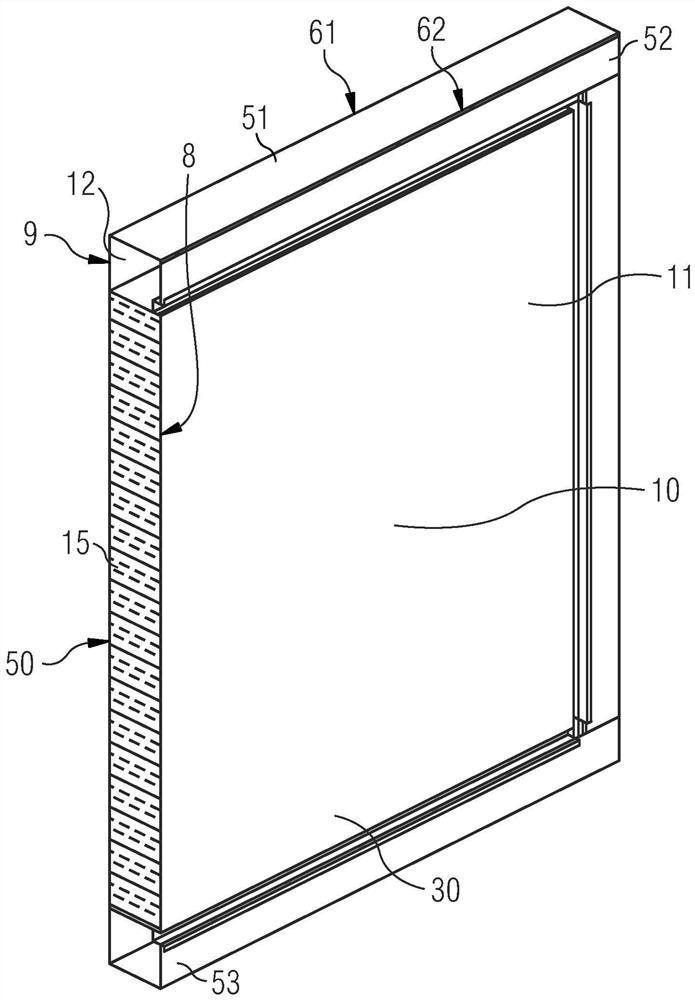
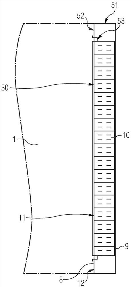
[0032] figure 1 Shown is a door 10 , not fully shown, of the air conditioning cabinet 1 , by means of which the (not shown) interior of the (not shown) housing of the air conditioning cabinet 1 can be closed off. The door 10 has an inner side 8 and an outer side 9, wherein the inner side 8 faces the interior space and the outer side 9 faces the environment.
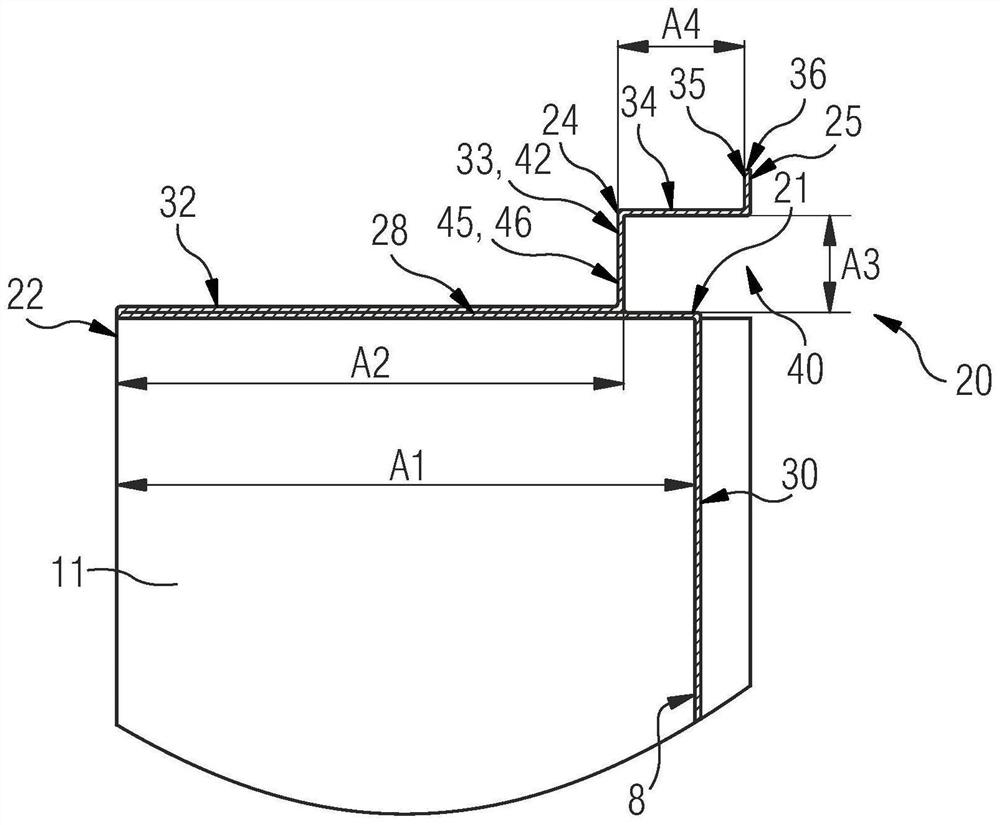
[0033] The door 10 has an inner wall 11 and an outer wall 12 which may each preferably be produced from a plate-shaped and bendable base body. The plate-shaped and bendable base may be made of a stainless steel plate and, as will be described in detail below, has a plurality of edges 21, 22, 23, 24, 25, 61, 62, the plurality of edges 21, 22, 23 , 24, 25, ...
PUM
 Abstract
Description
Claims
Application Information
 - Generate Ideas
- Intellectual Property
- Life Sciences
- Materials
- Tech Scout
- Unparalleled Data Quality
- Higher Quality Content
- 60% Fewer Hallucinations
Browse by: Latest US Patents, China's latest patents, Technical Efficacy Thesaurus, Application Domain, Technology Topic, Popular Technical Reports.
© 2025 PatSnap. All rights reserved.Legal|Privacy policy|Modern Slavery Act Transparency Statement|Sitemap|About US| Contact US: help@patsnap.com