
Building heat energy recovery equipment

A heat energy recovery and equipment technology, applied in the field of clean energy, can solve the problems of inconvenient disassembly and assembly, inconvenient to move and place, and cannot be disassembled in sections.

Active Publication Date: 2021-05-18
苏州市东挺河智能科技发展有限公司
View PDF7 Cites 0 Cited by
  • Summary
  • Abstract
  • Description
  • Claims
  • Application Information

AI Technical Summary

Problems solved by technology

[0004] In the above scheme, the indoor pipe laying is directly embedded in the building, which is inconvenient to move and place. The pipe is not designed separately, which is inconvenient to disassemble and cannot be disassembled in sections, which reduces the work efficiency

Method used


Image

  • Building heat energy recovery equipment
  • Building heat energy recovery equipment
  • Building heat energy recovery equipment

Examples


Embodiment Construction

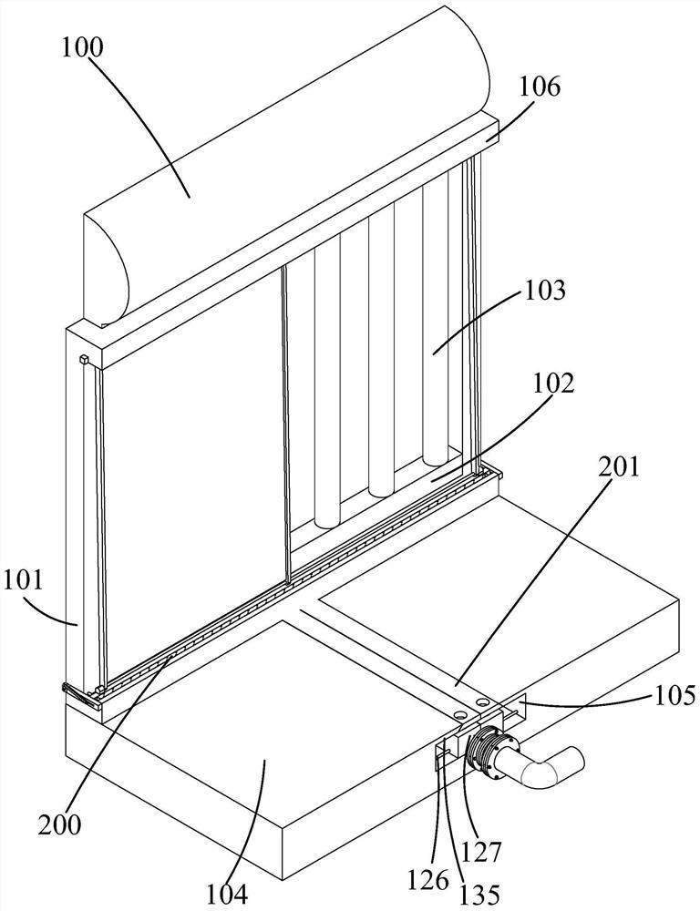
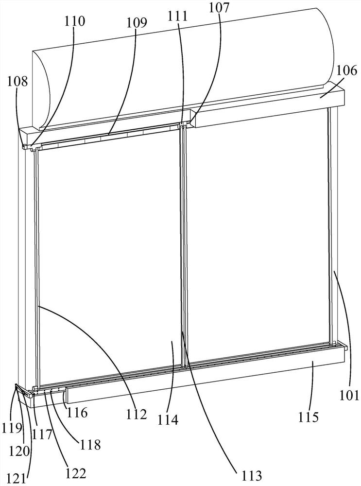
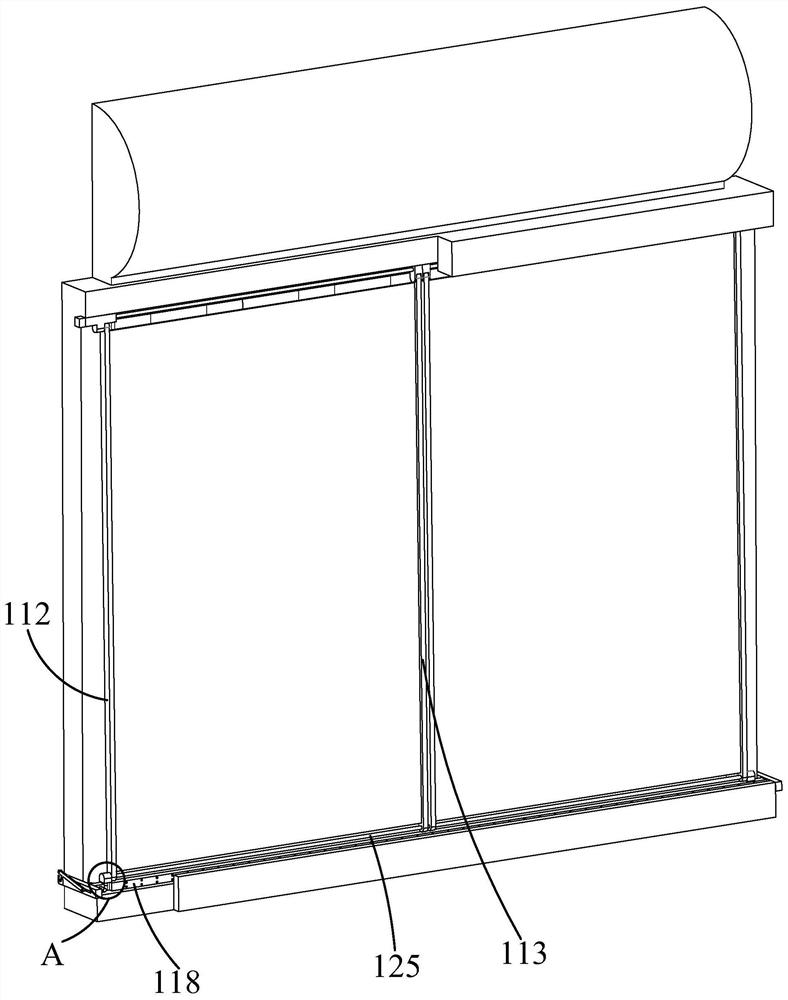
[0030] Such as Figure 1-Figure 9 As shown, the present invention is described in detail. For the convenience of description, the orientations mentioned below are now stipulated as follows: figure 1 The up, down, left, right, front and back directions of the projection relationship are consistent. A building heat energy recovery device of the present invention includes a water storage tank 100, an equipment rack 101 is fixed below the water storage tank 100, and a hot water pipe rack 102 is fixed inside the equipment rack 101. A number of solar hot water pipes 103 are fixed on the water pipe rack 102, and a shielding assembly 200 is arranged on one side of the equipment rack 101 to cover the equipment to prevent rainwater and smash hail through reciprocating motion. Block 104, the embedding block 104 is provided with an embedding chamber 105, and the embedding chamber 105 is provided with a pipe embedding assembly 201 for embedding pipes.

[0031] Beneficially, wherein, the s...


PUM


Abstract

The invention discloses building heat energy recovery equipment which structurally comprises a water storage tank. An equipment frame is fixedly arranged below the water storage tank; a hot water pipe frame is fixedly arranged in the equipment frame; a plurality of solar hot water pipes are fixedly arranged on the hot water pipe frame; a shielding assembly which is used for shielding the equipment to prevent rainwater and can mash hail through reciprocating motion is arranged on one side of the equipment frame; a burying block is fixedly arranged below the equipment frame; a burying cavity is formed in the burying block; and a pipeline burying assembly used for burying a pipeline is arranged in the burying cavity. According to the building heat energy recovery equipment provided by the invention, heat of sun irradiation can be conducted and collected into the pipeline, and then the pipeline is connected with a pipeline laid on the indoor ground, so that the heat can be brought into a room; indoor pipelines are not directly embedded into a building during laying, so that moving and placing are convenient; and the pipelines are independently designed so as to be convenient to disassemble and assemble and capable of being disassembled in sections.

Description

technical field [0001] The invention belongs to the technical field of clean energy, in particular to a building heat recovery device. Background technique [0002] The disadvantage of the existing technology is that the existing solar water heater technology can conduct the heat of the sun into the pipeline, and then use the pipeline to connect with the pipeline laid on the indoor ground, so that the heat of the sun can be brought into the room, but the indoor pipeline The laying is directly embedded in the building, which is inconvenient to move and place. The pipeline is not designed separately, and it is inconvenient to disassemble and assemble. It cannot be disassembled in sections. For this reason, people have carried out long-term exploration, put forward various solutions. [0003] For example, the Chinese patent literature discloses a large-diameter hot water pipe pipe jacking casing [application number: 201721733008.4], which includes a hot water pipe and a reinfo...

Claims


Application Information

Patent Timeline
Patent Type & Authority Applications(China)
IPC IPC(8): F24S20/00F24S10/70F24S40/10F24S40/20F24S80/30
CPCF24S20/00F24S10/70F24S40/10F24S40/20F24S80/30Y02E10/44
Inventor 刘波夏跃
Owner 苏州市东挺河智能科技发展有限公司
Learn More