
Water collector blade based on separation membrane, water collector and cooling tower

A separation membrane and water collector technology, applied in the fields of water collector blades, water collectors, and cooling towers, can solve problems such as long time consumption, difficulty in ensuring water vapor recovery rate and recovery efficiency, and reduced water collection capacity.

Pending Publication Date: 2021-05-18
SUN YAT SEN UNIV
View PDF3 Cites 2 Cited by
  • Summary
  • Abstract
  • Description
  • Claims
  • Application Information

AI Technical Summary

Problems solved by technology

Using water vapor to spontaneously condense into water flow, on the one hand, it takes a long time, on the other hand, it cannot well avoid the phenomenon of secondary entrainment of liquid droplets, water vapor will follow the loss of gas, and the water vapor recovery rate and recovery efficiency are difficult to guarantee
[0005] Chinese patent CN201104149Y discloses a cooling tower water vapor recovery device without power, which uses a mesh water eliminator made of sponge or fiber fabric to replace the traditional wave eliminator, and adds a cooling pool for further cooling of the cooling water. The water vapor recovery rate is improved to a certain extent, but as the sponge is soaked, the water collection capacity will be greatly reduced. Therefore, long-term use will aggravate the secondary entrainment of droplets or increase the manpower and material costs of sponge replacement.

Method used


Image

  • Water collector blade based on separation membrane, water collector and cooling tower
  • Water collector blade based on separation membrane, water collector and cooling tower
  • Water collector blade based on separation membrane, water collector and cooling tower

Examples


Embodiment 1

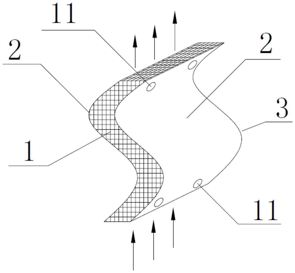
[0040] Such as figure 1 Shown is an embodiment of a water eliminator blade based on a separation membrane of the present invention, which includes a hydrophilic device 1 that collects droplets entrained in the air flow when the air flow passes through it using a hydrophilic component. A separation membrane 2 with hydrophilic and hydrophobic functions, the side of the separation membrane 2 with the hydrophilic function is attached to the hydrophilic device 1, and the side of the separation membrane 2 with the hydrophobic function is away from the hydrophilic device 1, and the droplets can pass through the separation The membrane 2 enters the hydrophilic device 1 .

[0041] As an embodiment of the present invention, the separation membrane 2 is a Janus membrane, and the Janus membrane includes a first membrane with a hydrophilic function and a second membrane with a hydrophobic function, and the first membrane and the second membrane are closely attached.

[0042] The hydrophil...

Embodiment 2

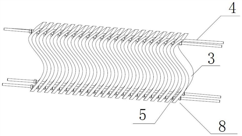
[0054] Such as figure 2 Shown is an embodiment of a cooling tower water eliminator based on a separation membrane of the present invention, including several water eliminator blades 3 based on a separation membrane 2 as described above, used to connect several water eliminator blades 3 and used to make the water eliminator The water receiver 8 can be fixed on the fixing device 4 in the cooling tower. A plurality of water eliminator blades 3 are sequentially staggered and partially overlapped on the fixing device 4. The water eliminator blades 3 are connected with the fixing device 4, and the adjacent water collectors Separation membrane channels 5 are formed between the vanes 3 of the device.

[0055] The fixing device 4 is used for arranging and connecting a plurality of water eliminator blades 3 based on the separation membrane 2 in order to form a water eliminator 8 composed of several water eliminator blades 3 . The collection of liquid droplets in the hot and humid air ...

Embodiment 3

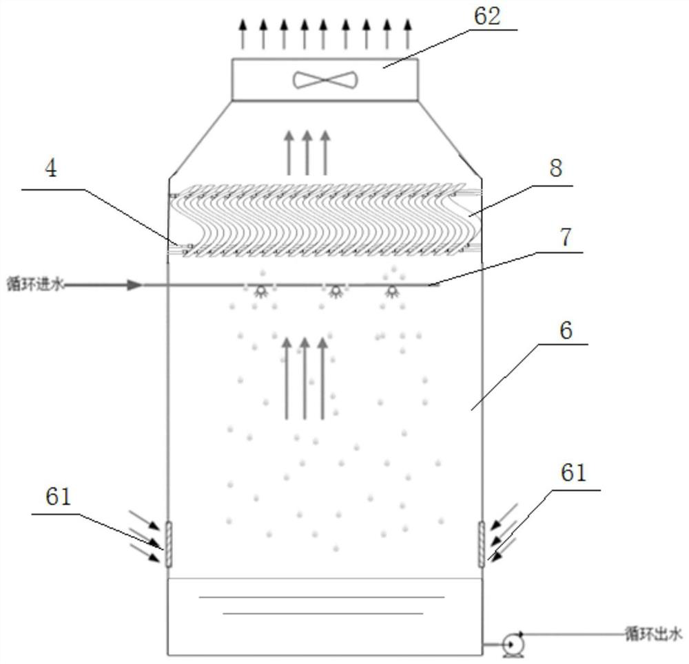
[0063] Such as image 3 Shown is an embodiment of a cooling tower based on a separation film of the present invention, including a cooling tower body 6, an air inlet 61 and an air outlet 62 are arranged on the cooling tower body 6, and the air inlet 61 is arranged at the lower part of the cooling tower body 6 , the air outlet 62 is arranged on the top of the cooling tower body 6, and the spray device 7 is arranged in the cooling tower body 6, and the cooling tower water eliminator 8 based on the separation film as above is arranged between the air outlet 62 and the spray device 7 ; The air flow enters the cooling tower body 6 from the air inlet 61 and then flows through the spray device 7 and the water collector 8 and then flows out from the air outlet 62 .

[0064] The cooling tower body 6 provides a cooling place; the spray device 7 realizes the filtering and cooling functions, but it will cause a lot of water to be mixed in the waste gas; the cooling tower water eliminator ...


PUM


Abstract

The invention relates to the technical field of water vapor recycling of cooling towers in power plants and chemical plants, in particular to a water collector blade based on a separation membrane, a water collector and a cooling tower. The water collector blade based on the separation membrane comprises a hydrophilic device, and the separation membrane with hydrophilic and hydrophobic functions is movably arranged at the outer side of the hydrophilic device. The side, with the hydrophilic function, of the separation membrane is attached to the hydrophilic device, the side, with the hydrophobic function, of the separation membrane deviates from the hydrophilic device, and liquid drops can penetrate through the separation membrane to enter the hydrophilic device. According to the water collector blade based on the separation membrane, the hydrophilic device arranged in the water collector blade is used for collecting moisture of airflow flowing through the hydrophilic device, and the separation membrane which is arranged outside the hydrophilic device and has opposite wettability physical performance is used for collecting moisture of airflow flowing out of the water collector blade. The recovery rate of water vapor is improved to the maximum extent, and the secondary entrainment phenomenon of liquid drops is reduced.

Description

technical field [0001] The invention relates to the technical field of water vapor recovery and utilization of cooling towers in power plants and chemical plants, and more specifically, to a water eliminator blade, a water eliminator, and a cooling tower based on a separation membrane. Background technique [0002] Cooling towers are widely used in electric power, chemical industry, petroleum, metallurgy and other industries. They are important devices for cooling circulating water. However, during the operation of open cooling towers, various water losses are always accompanied, such as wind loss, evaporation loss, etc. , for power plants, evaporation loss and wind blowing loss account for 30% to 70% of the total water consumption of the power plant, and the water loss is serious; according to statistics, the water loss of a 600MW thermal power plant is as high as 1000t / h, and the annual direct economic loss reaches more than 14 million yuan ; It can be seen that water savi...

Claims


Application Information

Patent Timeline
Patent Type & Authority Applications(China)
IPC IPC(8): F28F25/00
CPCF28F25/00F28F2025/005F28F2245/02F28F2245/04
Inventor 陈清林汤涯吴志勇张冰剑何畅
Owner SUN YAT SEN UNIV
Learn More