Check patentability & draft patents in minutes with Patsnap Eureka AI!

Ground fault detection device

A technology for grounding faults and detection devices, which is used in electrical devices, testing electrical devices in transportation, short-circuit testing, etc., and can solve problems such as inability to calculate insulation resistance RL

Pending Publication Date: 2021-05-18
YAZAKI CORP
View PDF1 Cites 0 Cited by
  • Summary
  • Abstract
  • Description
  • Claims
  • Application Information

AI Technical Summary

Problems solved by technology

Since the control device 510 usually sets the positive potential as the measurement range, in this case, the voltage measured by the control device 510 becomes 0, and the insulation resistance RL cannot be calculated

Method used


Image

  • Ground fault detection device
  • Ground fault detection device
  • Ground fault detection device

Examples


Embodiment Construction

[0062]

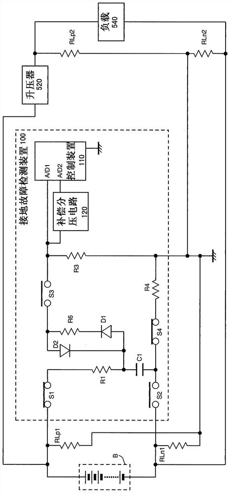
[0063] Hereinafter, a ground fault detection device according to an embodiment of the present invention will be described with reference to the accompanying drawings. figure 1 is a block diagram showing the configuration of the ground fault detection device 100 of the present embodiment. The ground fault detection device 100 is a device that is connected to an ungrounded battery B that supplies electric power to a load 540 , and detects a ground fault of a system provided with the battery B and the booster 520 . The ground fault detection device 100, the booster 520, the load 540, etc. are controlled by an external control device (not shown) as a high-level device.

[0064] Here, the insulation resistance between the output side of battery B (ie, the primary side of the positive electrode) and ground is denoted as RLp1, and the insulation resistance between the negative electrode and ground is denoted as RLn1. In addition, the insulation resistance between the out...


PUM


Abstract

A ground fault detection device includes: a capacitor operating as a flying capacitor; a first switching unit for switching between a state in which a positive electrode side of a battery and a first electrode plate of the capacitor are connected in series via a resistance, and a state in which the first electrode plate of the capacitor is connected to the ground via a measurement resistance; a second switching unit for switching between a state in which a negative electrode side of a high-voltage battery and a second electrode plate of a detection capacitor are connected in series via a resistance, and a state in which the second electrode plate of the detection capacitor is connected to the ground via the resistance; a control unit for controlling the first switching unit and the second switching unit; and an offset voltage divider circuit that divides and offsets the voltage generated in the measurement resistance. The control unit has a first port for receiving an input of a voltage generated in the measurement resistance and a second port for receiving an input of a voltage output from the offset voltage divider circuit.

Description

technical field [0001] The invention relates to a ground fault detection device using a flying capacitor. Background technique [0002] In a vehicle such as a hybrid vehicle or an electric vehicle including an engine and an electric motor as driving sources, a battery mounted on a vehicle body is charged, and electric power supplied from the battery is used to generate driving force. Typically, a power supply circuit involving a battery is configured as a high voltage circuit that handles a high voltage of 200V or more. To ensure safety, the high-voltage circuit including the battery has an ungrounded structure that is electrically insulated from the vehicle body serving as a ground reference potential point. [0003] Furthermore, there is a vehicle including a booster that boosts a positive potential of a battery and supplies the boosted positive potential of the battery to a load to improve drive efficiency of the load. In a vehicle equipped with a booster, the output of...

Claims


Application Information

Patent Timeline
IPC IPC(8): G01R31/52
CPCG01R31/006G01R31/52B60L3/0069G01R31/007B60L3/0046G01R31/12
Inventor 高松宽彰河村佳浩有谷亮介
Owner YAZAKI CORP
Features
  • R&D
  • Intellectual Property
  • Life Sciences
  • Materials
  • Tech Scout
  • Unparalleled Data Quality
  • Higher Quality Content
  • 60% Fewer Hallucinations
Learn More