Electricity-gas coupling network energy flow solving method considering state variables of energy station

A state variable and gas coupling technology, applied in the field of multi-energy flow calculation of integrated energy systems, can solve problems such as complex algorithms and poor iterative convergence

Active Publication Date: 2021-05-18
SHANDONG UNIV +1
View PDF13 Cites 1 Cited by
  • Summary
  • Abstract
  • Description
  • Claims
  • Application Information

AI Technical Summary

Problems solved by technology

Although the energy collection station model can simplify the modeling process of the equipment in the network, the above research has not fully considered the influence of the state variables of the energy collection station on the energy flow iteration in the multi-energy flow unified solution algorithm. The input of EH will change with the output of electricity and thermal loads, and the input of EH will cause the distribution of grid power flow and natural gas energy flow in IEGS. Therefore, the mul

Method used


Image

  • Electricity-gas coupling network energy flow solving method considering state variables of energy station
  • Electricity-gas coupling network energy flow solving method considering state variables of energy station
  • Electricity-gas coupling network energy flow solving method considering state variables of energy station

Examples


Embodiment 1

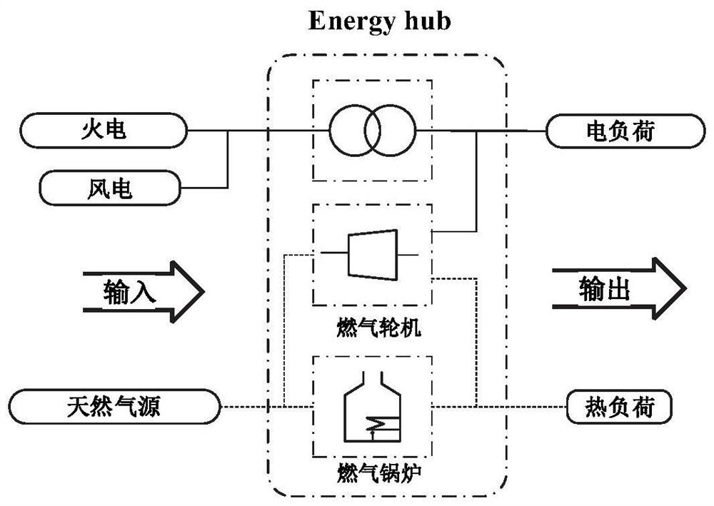
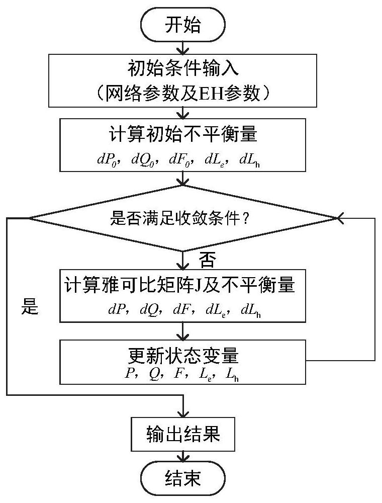
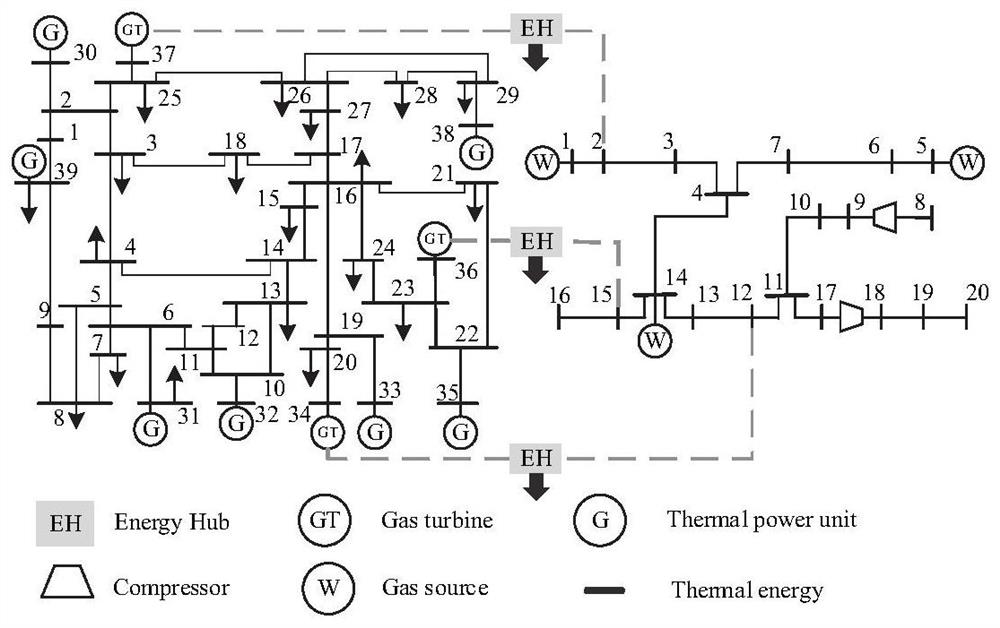
[0044]This embodiment discloses the energy flow solution method of the electric-gas coupling network considering the state variables of the energy collection station, establishes an energy collection station model that can reflect the coupling and conversion relationship between electricity and gas energy flow, and considers gas turbines and electric compressors in the network Machines and other equipment, on the basis of the state variables of the original subsystems, plus the input variables of electricity and gas and the output variables of electricity and heat of the energy collection station, the Jacobian matrix and iterative relationship were derived, and a unified solution model of IEGS multi-energy flow was established , combined with the modified IEEE39-node power system and the Belgian 20-node natural gas network for example verification. In addition, the comparative calculation of the gas network part according to different state description equations proves the effec...

Embodiment 2

[0088]The purpose of this embodiment is to provide a computing device, including a memory, a processor, and a computer program stored in the memory and operable on the processor. When the processor executes the program, the method in the first embodiment above is implemented. A step of.

Embodiment 3

[0090] The purpose of this embodiment is to provide a computer-readable storage medium.

[0091] A computer-readable storage medium, on which a computer program is stored, and when the program is executed by a processor, the steps of implementing the method in Example 1 are executed.


PUM


Abstract

The invention provides an electricity-gas coupling network energy flow solving method considering energy collection station state variables. The method comprises the steps that an energy collection station model capable of reflecting the electricity and gas energy flow coupling and conversion relation is established; based on an energy station model, considering a gas turbine and electric compressor equipment in a network, on the basis of original subsystem state variables, adding electricity and gas input variables and electricity and heat output variables of an energy station, deducing a Jacobian matrix and an iteration relation of the energy station, establishing an IEGS multi-energy-flow unified solving model, and establishing an IEGS multi-energy-flow unified solving model; and solving to obtain voltage, phase angle, node pressure and flow calculation results of the system. According to the multi-energy flow solving algorithm considering the EH state quantity, interaction between energy flows is considered, derivation of the Jacobian matrix is simplified, rapid convergence can be achieved, the number of algorithm iterations is reduced, and the calculation efficiency is improved.

Description

technical field [0001] The disclosure belongs to the field of multi-energy flow calculation of integrated energy systems, and in particular relates to a method for solving energy flow of an electric-pneumatic coupling network taking into account state variables of energy gathering stations. Background technique [0002] The statements in this section merely provide background information related to the present disclosure and do not necessarily constitute prior art. [0003] As a clean and environmentally friendly high-quality energy, natural gas is non-toxic and has a high calorific value. In recent years, the proportion of power generation through gas turbines has gradually increased, and the connection between the power system and the natural gas system has become closer and closer. Therefore, it is necessary to analyze the IEGS (Integrated Electricity and Natural Gas Systems) energy flow coupling and conversion relationship of electrical and gas subsystems. In addition, ...

Claims


Application Information

Patent Timeline
IPC IPC(8): G06F30/18G06F30/20G06Q50/06G06F113/04
CPCG06F30/18G06F30/20G06Q50/06G06F2113/04
Inventor 王辉张萌董雪涛徐志姜凡孔祥昊王成福
Owner SHANDONG UNIV
Why Eureka
Try Eureka