Laser radar chip packaging structure and packaging method

A chip packaging structure, laser radar technology, applied in the direction of instruments, semiconductor devices, circuits, etc., can solve problems such as difficult integration

Active Publication Date: 2021-05-18
NAT CENT FOR ADVANCED PACKAGING
View PDF2 Cites 2 Cited by
  • Summary
  • Abstract
  • Description
  • Claims
  • Application Information

AI Technical Summary

Problems solved by technology

[0004] The purpose of the present invention is to provide a laser radar chip packaging structure and packaging method to solve the problem that the existing laser radar chip packaging is not easy to integrate

Method used


Image

  • Laser radar chip packaging structure and packaging method
  • Laser radar chip packaging structure and packaging method
  • Laser radar chip packaging structure and packaging method

Examples


Embodiment Construction

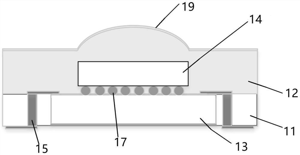
[0046] The laser radar chip packaging structure and packaging method proposed by the present invention will be further described in detail below in conjunction with the accompanying drawings and specific embodiments. Advantages and features of the present invention will be apparent from the following description and claims. It should be noted that all the drawings are in a very simplified form and use imprecise scales, and are only used to facilitate and clearly assist the purpose of illustrating the embodiments of the present invention.

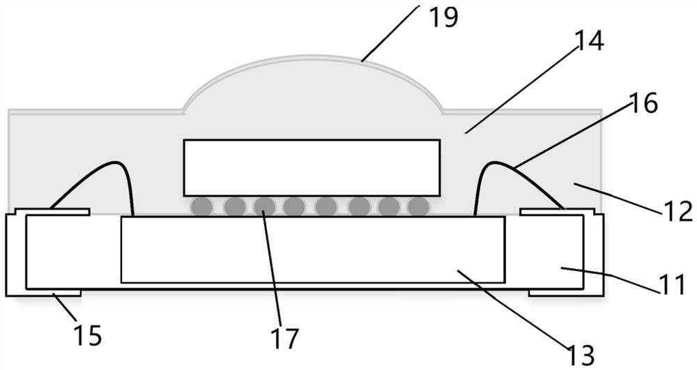
[0047] In addition, unless otherwise stated, features in different embodiments of the present invention can be combined with each other. For example, a feature in the second embodiment may be used to replace a corresponding or functionally identical or similar feature in the first embodiment, and the resulting embodiment also falls within the scope of disclosure or description of the present application.

[0048] The core idea of ​​the pres...


PUM


Abstract

The invention provides a laser radar chip packaging structure and method, and the structure comprises an optical chip which is disposed in a first packaging body, wherein the first packaging body is provided with a lens shape; and an electric chip which is arranged in a second packaging body, wherein the second packaging body is internally provided with a first electric interconnection structure, the first electric interconnection structure leads out the electric property of the electric chip, and the first packaging body and the second packaging body are arranged through a lamination layer.

Description

technical field [0001] The invention relates to the technical field of integrated circuit packaging, in particular to a laser radar chip packaging structure and packaging method. Background technique [0002] In applications such as autonomous driving and autonomous robots, LiDAR is a key component. With the popularity of lidar equipment, lidar chip packaging is also developing towards miniaturization. [0003] In the prior art, ceramic metal packaging is usually used to package the optical and electrical chips separately. The optical chip is packaged in a ceramic package with a light window, and the lens group and the emitting mirror are used to transmit and receive light in a specific direction. The corresponding control electronic chip and optical chip are packaged in two packages respectively. In this way, the packaging cost is high, the volume is large, and it is difficult to integrate. Contents of the invention [0004] The object of the present invention is to pr...

Claims


Application Information

Patent Timeline
Patent Type & Authority Applications(China)
IPC IPC(8): H01L25/16H01L23/31H01L21/50H01L21/56G01S7/481
CPCH01L25/167H01L23/3114H01L21/50H01L21/56G01S7/481
Inventor 孙瑜曹立强刘丰满
Owner NAT CENT FOR ADVANCED PACKAGING
Why Eureka
Try Eureka