Antenna structure and terminal equipment

A technology of antenna structure and terminal equipment, which is applied to antennas, slot antennas, antenna components, etc., and can solve problems such as complex feeding structures

Active Publication Date: 2021-05-18
BEIJING XIAOMI MOBILE SOFTWARE CO LTD
View PDF7 Cites 0 Cited by
  • Summary
  • Abstract
  • Description
  • Claims
  • Application Information

AI Technical Summary

Problems solved by technology

However, this feed needs to set an additional fixing device to fix the feed mechanism to achieve stable

Method used


Image

  • Antenna structure and terminal equipment
  • Antenna structure and terminal equipment
  • Antenna structure and terminal equipment

Examples


Embodiment Construction

[0046] Reference will now be made in detail to the exemplary embodiments, examples of which are illustrated in the accompanying drawings. When the following description refers to the accompanying drawings, the same numerals in different drawings refer to the same or similar elements unless otherwise indicated. The implementations described in the following exemplary examples do not represent all implementations consistent with the present invention. Rather, they are merely examples of apparatuses and methods consistent with aspects of the invention as recited in the appended claims.

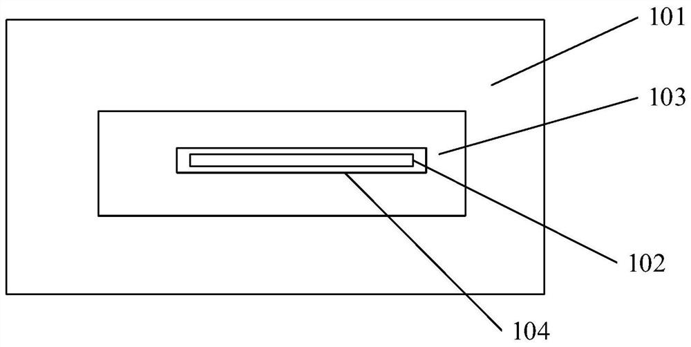
[0047] Figure 1a is a schematic diagram 1 of an antenna structure shown according to an exemplary embodiment. Such as Figure 1a As shown, the terminal equipment includes at least:

[0048] Part of the conductive shell 101 has a first gap 102;

[0049] The radiator 103 is arranged inside the conductive housing 101; wherein, the radiator 103 has a second slit 104, and the second slit 104 cover...


PUM


Abstract

The invention relates to an antenna structure and terminal equipment. The antenna structure is applied to the terminal equipment, and the antenna structure comprises a partial conductive shell which is provided with a first gap; and a radiator arranged on the inner side of the conductive shell, wherein the radiator is provided with a second gap, the second gap is covered on the first gap, and the radiator and the conductive shell can be coupled at the first gap and the second gap to form an antenna for receiving and transmitting at least one frequency band. According to the embodiment of the invention, the wireless signal is transmitted and received through the coupling of the radiator and the conductive shell, and the use of a spring needle or an elastic sheet and other type of feed mechanisms can be avoided, so that the feed structure and the installation process required for transmitting and receiving the wireless signal at the first gap of the conductive shell are simplified, and the antenna manufacturing efficiency is improved.

Description

technical field [0001] The present disclosure relates to the technical field of wireless communication, and in particular to an antenna structure and a terminal device. Background technique [0002] The slot antenna is to open a slot on the waveguide, metal plate, coaxial line or resonant cavity, and the electromagnetic wave radiates to the external space through the slot. Existing slot antennas are usually fed through a feeding mechanism. For example, the slot antenna is fed through the pogo pins or shrapnel contained in the feeding mechanism. However, this feed needs to set an additional fixing device to fix the feed mechanism to achieve stable contact between the feed mechanism and the main board, and there is a problem that the feed structure is complicated. Contents of the invention [0003] The present disclosure provides an antenna structure and a terminal device. [0004] In the first aspect of the embodiments of the present disclosure, an antenna structure is p...

Claims


Application Information

Patent Timeline
IPC IPC(8): H01Q1/36H01Q13/10H01Q1/22H01Q1/24
CPCH01Q1/36H01Q13/10H01Q1/2258H01Q1/242
Inventor 胡茂程胜祥
Owner BEIJING XIAOMI MOBILE SOFTWARE CO LTD
Why Eureka
Try Eureka