
Dual-purpose power supply base

A power supply base, dual-purpose technology, applied in the direction of circuits, electrical components, contact parts, etc., can solve the problems of unsightly, damaged walls, inconvenient use of power cords, etc.

Pending Publication Date: 2021-05-18
JINJIANG DONGSHENG TIMEKEEPER ELECTRONICS
View PDF0 Cites 0 Cited by
  • Summary
  • Abstract
  • Description
  • Claims
  • Application Information

AI Technical Summary

Problems solved by technology

[0004] The purpose of the present invention is to provide a dual-purpose power supply stand to solve the inconvenience and unsightly use of electronic products currently hung on the wall because the power cord cannot be plugged into the power socket Inconvenient use due to nailed hooks, damaged walls and unsightly use

Method used


Image

  • Dual-purpose power supply base
  • Dual-purpose power supply base
  • Dual-purpose power supply base

Examples


Embodiment Construction

[0018] In order to further explain the technical solution of the present invention, the present invention will be described in detail below through specific examples.

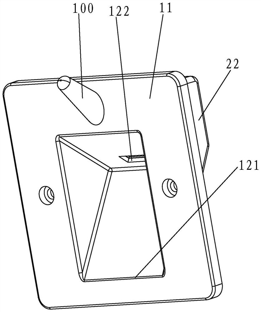
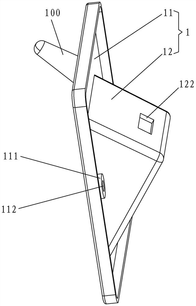
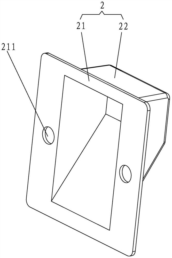
[0019] A dual-purpose power supply stand of the present invention, such as Figure 1-3 shown, including housing and power supply circuit

[0020] (not shown in the figure), the power supply circuit is installed in the housing, and the front of the housing is concavely provided with a receiving cavity, and the input end of the power supply circuit has an AC terminal extending out of the back of the housing (not shown in the figure output), the output end of the power supply circuit has a plug-in power supply connector and a wireless power supply plug 100, the power supply principle of the plug-in power supply connector, wireless power supply plug 100 and the power supply circuit is well known, and it is not an improvement of the applicant. The power supply mode of the power supply plug 100 is the same as the po...


PUM


Abstract

A dual-purpose power supply base of the present invention comprises a shell and a power supply circuit located in the shell, an accommodating concave cavity is formed in the front face of the shell in a backward concave manner, and the power supply circuit is provided with an alternating current binding post. The output end of the power supply circuit is provided with a pluggable power supply connector and a wireless power supply plug, and the wireless power supply plug extends out of the front face of the shell and is arranged in an upward inclined manner. The wireless power supply plug is located above the accommodating concave cavity, a power supply window for exposing the pluggable power supply connector is formed in the inner cavity wall of the accommodating concave cavity, and the shell is provided with an installation structure used for being installed on a wall wiring cassette. Compared with the prior art, the wireless power supply plug directly extends into a concave hole in the back surface of an electronic product during application, so that the commercial power can supply power to the electronic product, the use is convenient; no part except the electronic product is exposed on the whole wall surface, so that the use is attractive; and the wireless power supply plug also has a hooking effect on the electronic product, so that a hanging lug and a hook do not need to be additionally arranged on a wall and the electronic product, and the use is more convenient.

Description

technical field [0001] The invention relates to the field of power supply, in particular to a power supply stand. Background technique [0002] As we all know, when using electronic products that are hung on the wall, a hook needs to be nailed on the wall separately before they can be hung on the wall. The electric plug of the power socket can only be used with electricity. However, if the power cord of the electronic product is short and cannot be plugged into the pre-buried power socket on the wall, another power strip needs to be introduced separately, which is inconvenient to use and affects the overall appearance of the use, and the exposed power cord also damages the The overall use is beautiful; and the hook on the wall damages the wall on the one hand, and the hook makes the whole wall less aesthetically pleasing when there is no electronic product on the other hand. [0003] In view of this, the inventor has carried out in-depth research on the above-mentioned pro...

Claims


Application Information

Patent Timeline
Patent Type & Authority Applications(China)
IPC IPC(8): H01R13/73H01R27/02H01R13/04
CPCH01R13/04H01R13/73H01R27/02
Inventor 施自强林家利
Owner JINJIANG DONGSHENG TIMEKEEPER ELECTRONICS
Learn More