A Live Compensation Tool for Transmission Lines

A technology of transmission lines and tools, which is applied in the direction of overhead lines/cable equipment, etc., can solve problems such as cumbersome operation methods, low reimbursement efficiency, and high operation risk, so as to improve reimbursement efficiency, strong adaptability, and ensure reimbursement quality effect

Active Publication Date: 2022-04-26
HUAIBEI POWER SUPPLY COMPANY OF STATE GRID ANHUI ELECTRIC POWER +1
View PDF10 Cites 0 Cited by
  • Summary
  • Abstract
  • Description
  • Claims
  • Application Information

AI Technical Summary

Problems solved by technology

Since the position where the cotter pin is missing is on the wire side and is blocked by the insulator, it is relatively far away from the cross arm. The operator needs to work live (equal potential) and move to the position where the cotter pin is missing with the help of an insulating hard or soft ladder. The working method There are disadvantages of cumbersome process, low efficiency, long operation time, high labor intensity and high operation risk
For example, the Chinese Utility Model Patent Publication No. CN202906295U discloses a refitting tool for the cotter pin of a power transmission line, wherein it is disclosed that the refitting of the cotter pin is realized through the cooperation of the compensator and the insulating operating rod, but before the refitting of the cotter pin It is fixed at the end of the compensator. After the cotter pin is put into the pin hole, since the cotter pin and the end of the compensator are fixed, it is easy to take the cotter pin out of the pin hole synchronously when the compensator is taken out, and it needs to be re-compensated. Pin operation, manual long-term operation is prone to fatigue, resulting in low reimbursement efficiency

Method used


Image

  • A Live Compensation Tool for Transmission Lines
  • A Live Compensation Tool for Transmission Lines
  • A Live Compensation Tool for Transmission Lines

Examples


Embodiment Construction

[0027] In order to facilitate those skilled in the art to understand the technical solution of the present invention, the technical solution of the present invention will be further described in conjunction with the accompanying drawings.

[0028] In this application, terms such as "installation", "connection", "connection" and "fixation" should be interpreted in a broad sense, for example, it can be a fixed connection or a detachable connection, unless otherwise clearly specified and limited. , or integrated; it can be a mechanical connection, an electrical connection, or a communication; it can be a direct connection or an indirect connection through an intermediary, it can be the internal communication of two components or the interaction relationship between two components . Those of ordinary skill in the art can understand the specific meanings of the above terms in this application according to specific situations.

[0029] In this application, unless otherwise clearly ...


PUM


Abstract

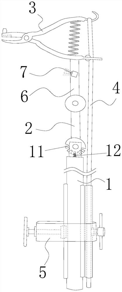
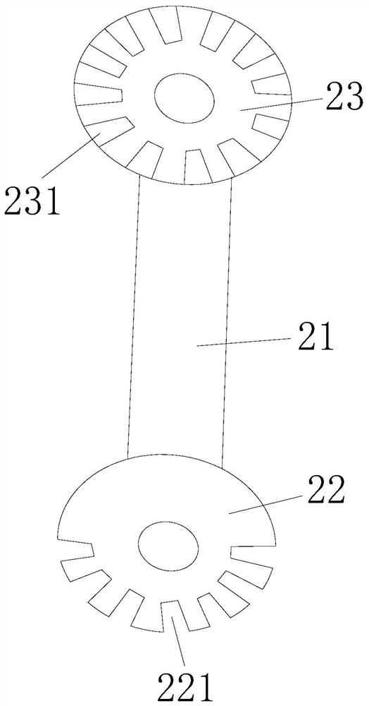
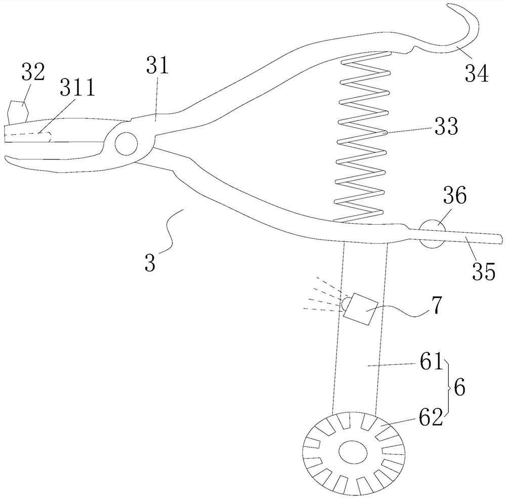
The invention discloses a power transmission line live compensation tool, which comprises an insulating rod, a rotating rod, a compensation device, an insulating rope and a clamping device. A rotating rotating rod is fixed on the top of the insulating rod, and the rotating rod is far away from One end of the insulating rod is fixed with a compensation device capable of clamping a cotter pin, one end of the compensation device is connected to an insulating rope, the bottom of the insulating rod is fixed with a clamping device capable of clamping the insulating rope, and the insulating rope is tightened The offset pin is caused to clamp the cotter pin, and the clamping device is loosened to loosen the insulating rope, thereby causing the offset pin to break away from the cotter pin. The advantage of the present invention is that the tool can prevent the ejection pin from being taken away by the compensation device in reverse, greatly improving the success rate of compensation, reducing the working intensity of the operator, ensuring the quality of compensation, and improving the efficiency of compensation. It can also be quickly aligned with the supplementary pin hole, which has strong applicability.

Description

technical field [0001] The invention relates to the technical field of power transmission line maintenance tools, in particular to a power transmission line live compensation tool. Background technique [0002] With the rapid development of economy and society, the demand for power load is increasing year by year, and the scale of transmission lines is also increasing. There are more and more defects such as corrosion and falling of cotter pins of connecting hardware bolts, which seriously affect the safe and stable operation of transmission lines. Transmission line operation management regulations stipulate that the lack of cotter pins for connecting fittings is a crisis defect, and the time required to deal with defects should not exceed 24 hours. Supplementing cotter pins has become one of the busiest operations of the line team. Since the position where the cotter pin is missing is on the wire side and is blocked by the insulator, it is relatively far away from the cros...

Claims


Application Information

Patent Timeline
Patent Type & Authority Patents(China)
IPC IPC(8): H02G1/02
CPCH02G1/02
Inventor 张涛王飞林张浩然朱格兵沈毅王飞张爱萍
Owner HUAIBEI POWER SUPPLY COMPANY OF STATE GRID ANHUI ELECTRIC POWER
Why Eureka
Try Eureka