Control method of flywheel array energy storage system, energy storage system and power grid system

A technology of an energy storage system and a control method, which is applied in the field of power grids and can solve problems such as the limitation of the number of flywheels, the reduction of the reliability of the flywheel array energy storage system, and the increase of the operating load of the total controller.

Inactive Publication Date: 2021-05-18
沈阳微控新能源技术有限公司
View PDF10 Cites 0 Cited by
  • Summary
  • Abstract
  • Description
  • Claims
  • Application Information

AI Technical Summary

Problems solved by technology

[0004] As the number of single flywheels connected to the power grid increases, the amount of two-way communication data will increase, and the number of power commands for the single flywheels by the general controller and the differential adjustment of the energy storage status of the single flywheels will also increase. Increase the operating load of the total controller, so subject to the processing capacity

Method used


Image

  • Control method of flywheel array energy storage system, energy storage system and power grid system
  • Control method of flywheel array energy storage system, energy storage system and power grid system
  • Control method of flywheel array energy storage system, energy storage system and power grid system

Examples


Embodiment Construction

[0034] Embodiments of the present invention are described in detail below, and the embodiments described with reference to the drawings are exemplary, and embodiments of the present invention are described in detail below.

[0035] Refer below Figure 1-Figure 4 A control method of a flywheel array energy storage system according to an embodiment of the present invention is described.

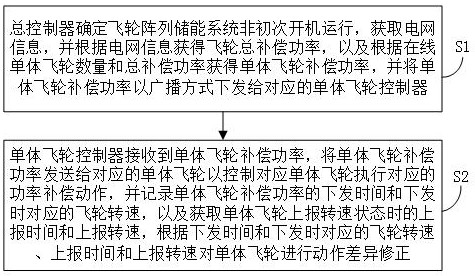
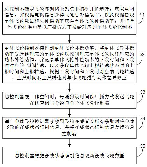
[0036] figure 1 It is a flow chart of the control method of the flywheel array energy storage system in one embodiment of the present invention.

[0037] In some embodiments of the present invention, the flywheel array energy storage system includes an acquisition module, N individual flywheels, a general controller, and N individual flywheel controllers connected to the N individual flywheels in one-to-one correspondence, where N is greater than An integer of 1, for example, N can be 2, 10, 100 or 200, etc. The acquisition module is used to collect grid information and transmit the grid inf...


PUM


Abstract

The invention discloses a control method of a flywheel array energy storage system, the flywheel array energy storage system and a power grid system. The method comprises: a master controller determining that the flywheel array energy storage system is not started for operation for the first time, and obtaining flywheel total compensation power according to obtained power grid information; obtaining single flywheel compensation power according to the number of online single flywheels and the total compensation power of the flywheels, and issuing the single flywheel compensation power to a corresponding single flywheel controller in a broadcast mode; the single flywheel controller receiving the single flywheel compensation power and sending the single flywheel compensation power to the corresponding single flywheel so as to control the corresponding single flywheel to execute the corresponding power compensation action, and recording the issuing time of the single flywheel compensation power and the corresponding flywheel rotating speed during issuing; and acquiring the reporting time and the reporting rotating speed when the single flywheel reports the rotating speed state, and performing action difference correction on the single flywheel according to the issuing time and the flywheel rotating speed, the reporting time and the reporting rotating speed corresponding to the issuing time. The method can improve the system stability, shorten the response time and increase the capacity expansion amount.

Description

technical field [0001] The invention relates to the technical field of power grids, in particular to a control method for a flywheel array energy storage system, a flywheel array energy storage system and a power grid system. Background technique [0002] As people pay more and more attention to energy and environmental issues, renewable energy sources such as wind power and photovoltaic power generation have been widely used, but these renewable energy sources are volatile. The frequency will be unstable, and the power quality of the power supply cannot be guaranteed. By rationally configuring and controlling the power-type energy storage system, the dynamic performance of the power grid under the disturbance of fluctuating energy and the ability to deal with dynamic shocks can be improved, and its power in the power grid can be realized. Increased capacity reliability. Compared with traditional chemical battery energy storage, flywheel energy storage technology has the ad...

Claims


Application Information

Patent Timeline
IPC IPC(8): H02J3/30H02J13/00H02J15/00
CPCH02J3/30H02J13/00016H02J15/007H02J2203/10Y02E60/00Y02E60/16Y04S10/14Y04S40/124
Inventor 李海超王聪程祥
Owner 沈阳微控新能源技术有限公司
Why Eureka
Try Eureka