Valve holder

A holder and valve technology, which is applied in the field of medical devices, can solve the problems such as the complex structure of the valve holder, and achieve the effects of simple structure, convenient use and simple connection mechanism.

Pending Publication Date: 2021-05-25
GUANGDONG PULSE MEDICAL SCI & TECH CO LTD
View PDF0 Cites 4 Cited by
  • Summary
  • Abstract
  • Description
  • Claims
  • Application Information

AI Technical Summary

Problems solved by technology

[0004] The purpose of the present invention is to provide a valve holder to solve the technical problem of complex structure of the valve holder in the prior art to a certain extent

Method used


Image

  • Valve holder
  • Valve holder
  • Valve holder

Examples


Embodiment Construction

[0032] The technical solutions of the present invention will be clearly and completely described below in conjunction with the accompanying drawings. Apparently, the described embodiments are some of the embodiments of the present invention, but not all of them.

[0033] The components of the embodiments of the invention generally described and shown in the figures herein may be arranged and designed in a variety of different configurations. Accordingly, the following detailed description of the embodiments of the invention provided in the accompanying drawings is not intended to limit the scope of the claimed invention, but merely represents selected embodiments of the invention.

[0034] Based on the embodiments of the present invention, all other embodiments obtained by persons of ordinary skill in the art without making creative efforts belong to the protection scope of the present invention.

[0035] In the description of the present invention, it should be noted that the...


PUM


Abstract

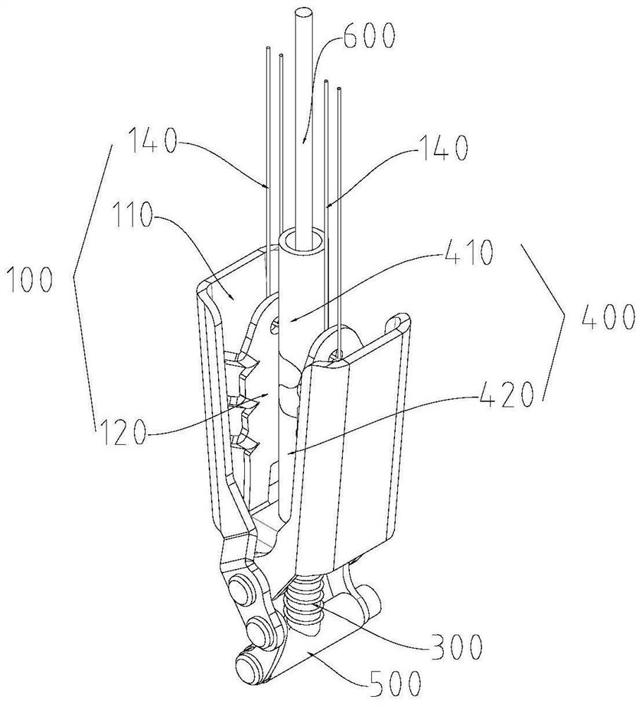
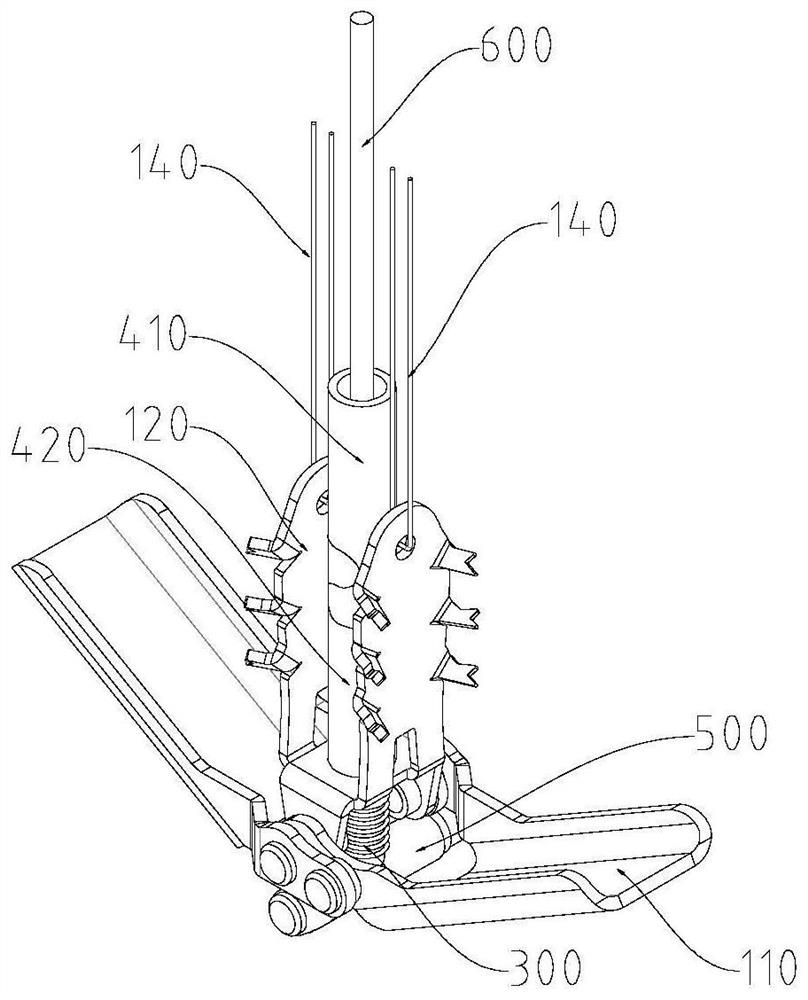
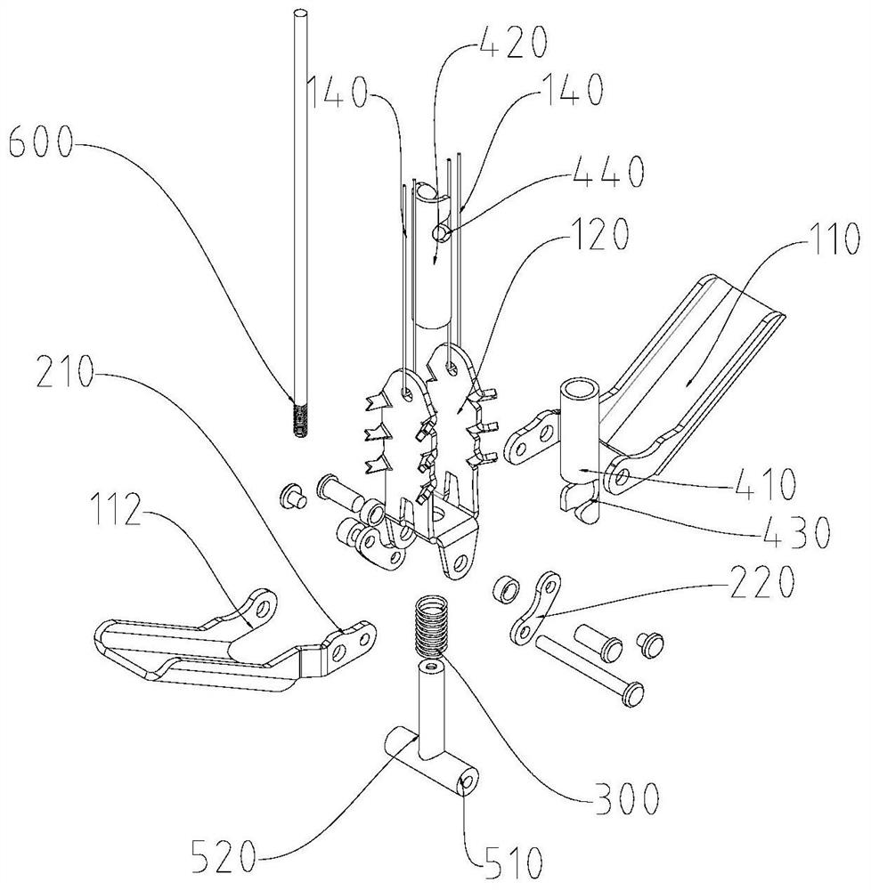
The invention relates to a valve holder. The valve holder comprises a clamping assembly, a connecting rod assembly, an elastic self-locking piece, a releasing assembly, a base and a driving shaft. The clamping assembly comprises a connecting plate, two clamping pieces and two clamping arms; the clamping assembly comprises a connecting plate, two clamping pieces and two clamping arms; the two clamping arms are rotationally connected, and the rotating joint of the two clamping arms is rotationally connected with the connecting plate. The two clamping pieces are oppositely arranged on the connecting plate; one of the two clamping arms is corresponding to one of the clamping pieces; one end of the first connecting piece is rotationally connected to the rotary joint of the clamping arm and the connecting plate, the other end of the first connecting piece is rotationally connected with one end of the second connecting piece, and the other end of the second connecting piece is rotationally connected with the base; the elastic self-locking piece is connected between the base and the clamping assembly, so that the clamping assembly and the base can be reset; the driving shaft penetrates through the releasing assembly to be in threaded connection with the base so as to drive the base to move.

Description

technical field [0001] The invention relates to the technical field of medical instruments, in particular to a valve holder. Background technique [0002] The mitral valve is a two-piece valve attached to the periphery of the left atrium and ventricle, connected to the papillary muscle by the chordae, and prevents the blood from the left ventricle from flowing back to the left atrium. Mitral valve regurgitation (MR) is due to congenital abnormalities or acquired lesions, the left ventricle cannot be completely closed when the left ventricle contracts, so that part of the blood flowing from the left atrium into the left ventricle flows back to the left atrium, causing a series of cardiac changes and clinical symptoms, which can lead to heart failure in severe cases. The valve clamping device developed based on the principle of surgical valve edge-to-edge suture technology is currently the most affirmed because of its high safety, simple technical principle, and high feasibil...

Claims


Application Information

Patent Timeline
IPC IPC(8): A61F2/24A61B17/08A61B17/10
CPCA61B17/08A61B17/083A61B17/10A61F2/246A61F2/2466
Inventor 阮成民肖建平翟梦林
Owner GUANGDONG PULSE MEDICAL SCI & TECH CO LTD
Why Eureka
Try Eureka