
MEMS friction sensor automatic packaging device based on visual positioning technology

A technology for visual positioning and packaging equipment, applied in mechanical equipment, devices for coating liquid on surfaces, material gluing, etc. It can solve automatic dispensing, alignment error measurement, and friction measurement accuracy without considering MEMS friction sensors. To be further improved, consistency and accuracy to be improved and other issues to achieve the effect of improving accuracy

Active Publication Date: 2021-05-25
中国空气动力研究与发展中心超高速空气动力研究所
View PDF9 Cites 2 Cited by
  • Summary
  • Abstract
  • Description
  • Claims
  • Application Information

AI Technical Summary

Problems solved by technology

However, this method uses mechanical positioning and manual alignment, assembly, and packaging under a microscope, which requires manual participation throughout the process, and does not consider special requirements such as automatic dispensing of MEMS friction sensors and alignment error measurement, making the sensor assembly consistent The performance and accuracy need to be improved, resulting in the need to further improve the accuracy of friction measurement

Method used


Image

  • MEMS friction sensor automatic packaging device based on visual positioning technology
  • MEMS friction sensor automatic packaging device based on visual positioning technology
  • MEMS friction sensor automatic packaging device based on visual positioning technology

Examples


Embodiment Construction

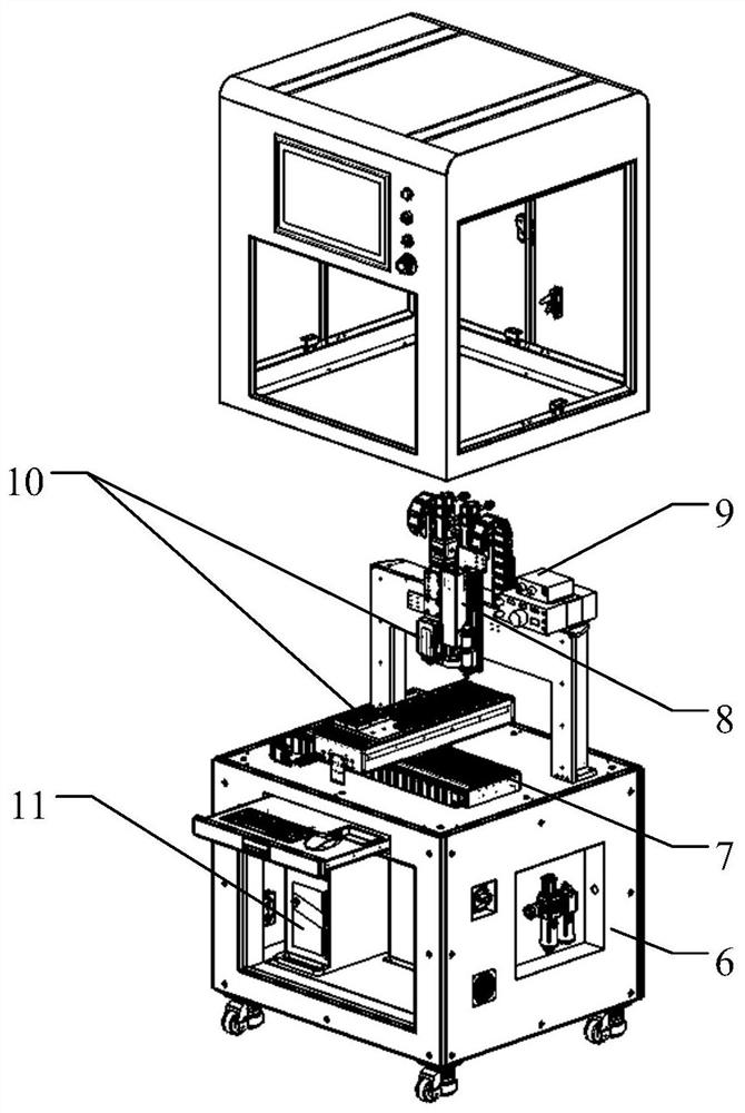
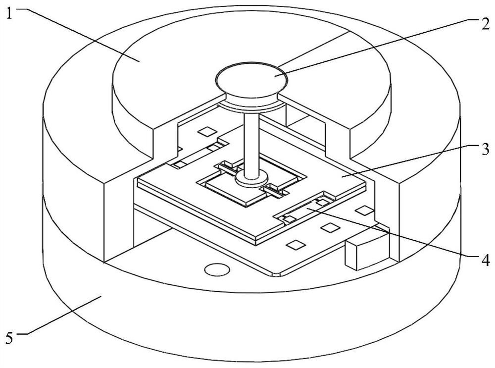
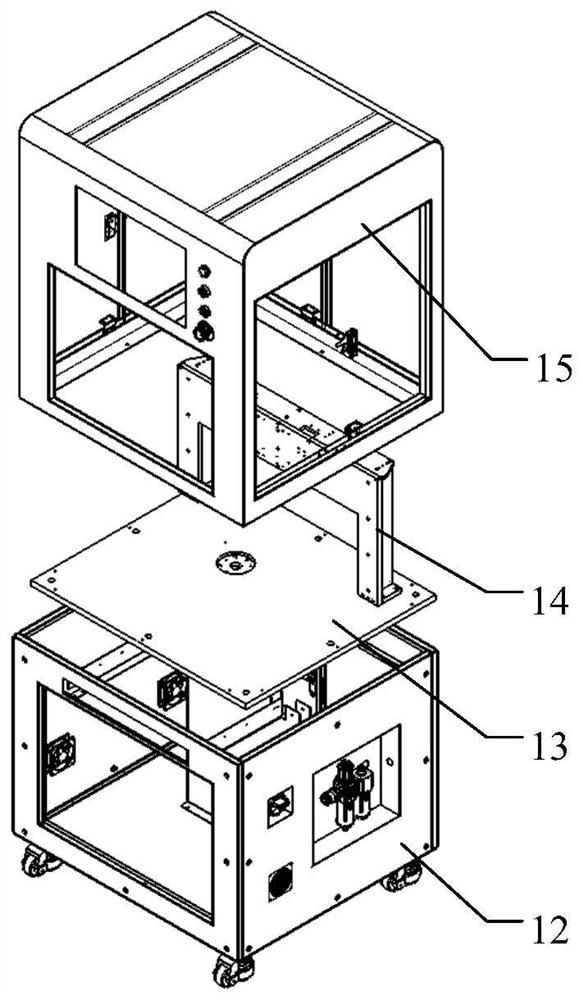
[0038] Attached below Figure 1-8 The present invention is further described with examples:

[0039] A MEMS friction sensor automatic packaging equipment based on visual positioning technology, including an equipment rack 6, a multi-axis precision motion module 7, a visual positioning module 8, an automatic dispensing module 9, a positioning and adsorption module 10 and a motion control module 11 , the equipment rack 6 includes a rack base 12, a rack bottom plate 13, a support plate frame 14 and a rack shell 15, the rack bottom plate 13 is locked and fixed on the top of the rack base 12 by bolts, and the support The plate frame 14 is fastened to the top of the rack bottom plate 13 by screw locking, the rack shell 15 is fastened to the top of the rack bottom plate 13 by bolt locking, and the equipment rack 6 is used to install the multi-axis precision motion module module 7. Vision module 8, automatic dispensing module 9, adsorption and positioning module 10 and motion control...


PUM


Abstract

The invention discloses an MEMS friction sensor automatic packaging device based on a visual positioning technology. An X-axis base is fixed on the top of a rack base plate, an X-axis guide rail and an X-axis sliding block are fixed on the X-axis base, the top of the X-axis sliding block is fixedly connected with the bottom of a Y-axis base, a visual positioning module comprises an upper camera mounting plate, an upper visual camera, an upper light source, a lower camera mounting plate, a lower visual camera and a lower light source, the upper camera mounting plate is fixedly connected with a U-axis sliding block, the upper visual camera and the upper light source are fixedly mounted at the outer side of the upper camera mounting plate, and the lower camera mounting plate is fixedly mounted on the rack base plate. According to the MEMS friction sensor automatic packaging device, the consistency and the precision of assembling and packaging of an MEMS friction sensor can be effectively improved, and then the precision of a surface friction measurement test of a hypersonic wind tunnel model is improved.

Description

technical field [0001] The invention relates to the technical field of MEMS sensor packaging in a micro-electromechanical system, in particular to a MEMS friction sensor automatic packaging device based on visual positioning technology. Background technique [0002] MEMS friction sensors are mainly used to measure the frictional resistance on the surface of the aircraft, and then determine the size and distribution of the frictional resistance on the surface of the aircraft, which is of great significance to the design of the aircraft. The traditional surface friction resistance test device is mainly a micro-strain friction balance, but it is difficult to be widely used in the field of aircraft design due to factors such as sensitivity, temperature, volume and cost. MEMS friction sensors based on MEMS technology have the outstanding advantages of small size, low cost and high reliability, and can be widely used in aircraft design and other fields. [0003] In 2014, the inve...

Claims


Application Information

Patent Timeline
IPC IPC(8): B05C5/02B05C11/10F16B11/00
CPCB05C5/02B05C11/10B05C11/1015F16B11/006
Inventor 王雄陈立国朱涛薛立伟许晓斌贾玉蝶王南天
Owner 中国空气动力研究与发展中心超高速空气动力研究所
Learn More