
Hydraulic machine with automatic induction safety protection device

A safety protection device and automatic sensing technology, applied in the hydraulic field, can solve the problems of easy displacement, hydraulic position dislocation of the workpiece, and reduced production quality of the workpiece, and achieve the effects of increasing friction, reducing position dislocation, and improving production quality.

Inactive Publication Date: 2021-05-25
李三源
View PDF0 Cites 0 Cited by
  • Summary
  • Abstract
  • Description
  • Claims
  • Application Information

AI Technical Summary

Problems solved by technology

[0002] When assembling hardware workpieces, the hydraulic press is used to press down the workpieces, place the workpieces horizontally on the top of the workbench, and the hydraulic cylinder drives the pressure rod to move down to press down the objects. In order to reduce the displacement of the workpieces during the hydraulic process, the workbench is equipped with The workpiece groove, the workpiece is placed in the workpiece groove; when the hydraulic machine is used to hydraulically process the workpiece in the prior art, because the volume of the workpiece is different, when the hydraulic workpiece is spherical, the contact area between the bottom of the spherical workpiece and the inner wall of the workpiece groove Small, when the pressure rod quickly presses down on the workpiece, the workpiece is easily displaced by the thrust of the pressure rod in an instant, causing the hydraulic position of the workpiece to be misaligned, resulting in a reduction in the production quality of the workpiece

Method used


Image

  • Hydraulic machine with automatic induction safety protection device
  • Hydraulic machine with automatic induction safety protection device
  • Hydraulic machine with automatic induction safety protection device

Examples


Embodiment 1

[0027] as attached figure 1 to attach Figure 5 Shown:

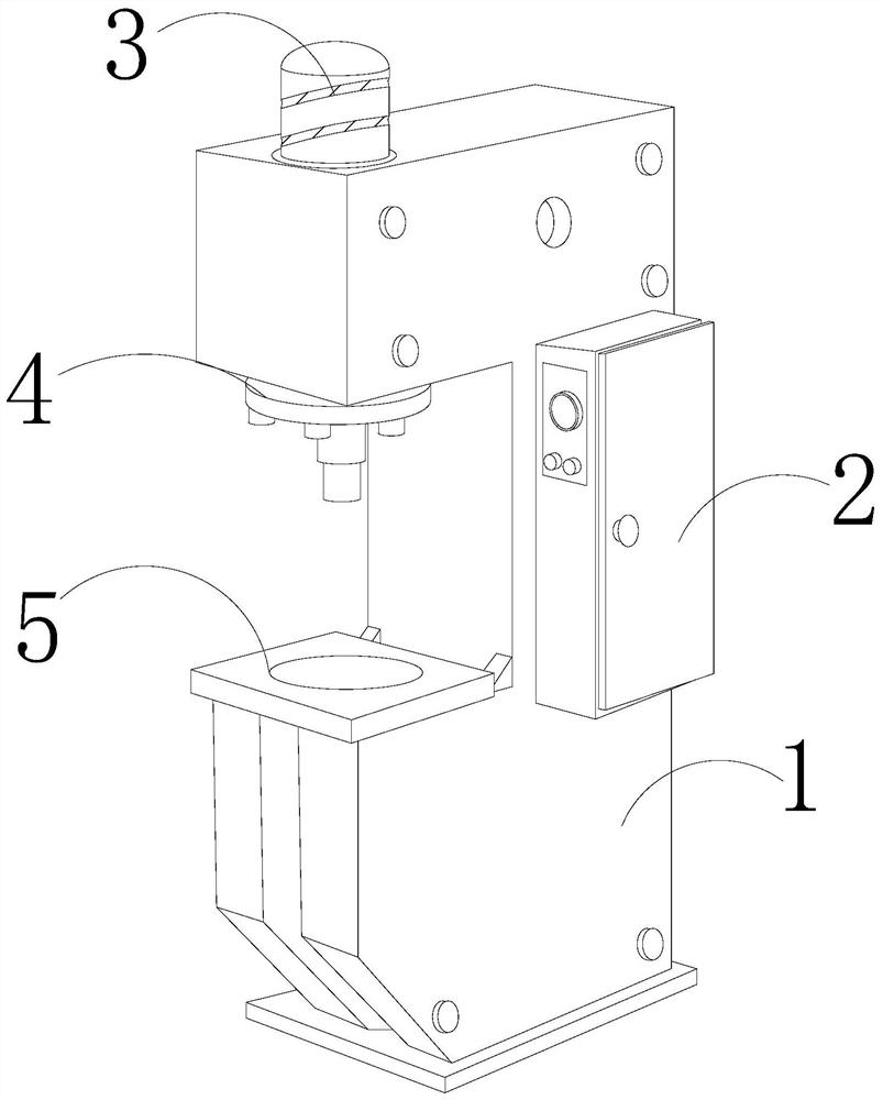
[0028] The present invention provides a hydraulic press with an automatic induction safety protection device, the structure of which includes a body 1, a controller 2, a hydraulic cylinder 3, a pressure rod 4, and a workbench 5. The controller 2 is arranged on the right side of the body 1, and the The hydraulic cylinder 3 is installed on the top of the body 1 , the pressure rod 4 is connected to the front bottom of the body 1 , and the workbench 5 is arranged below the pressure rod 4 .

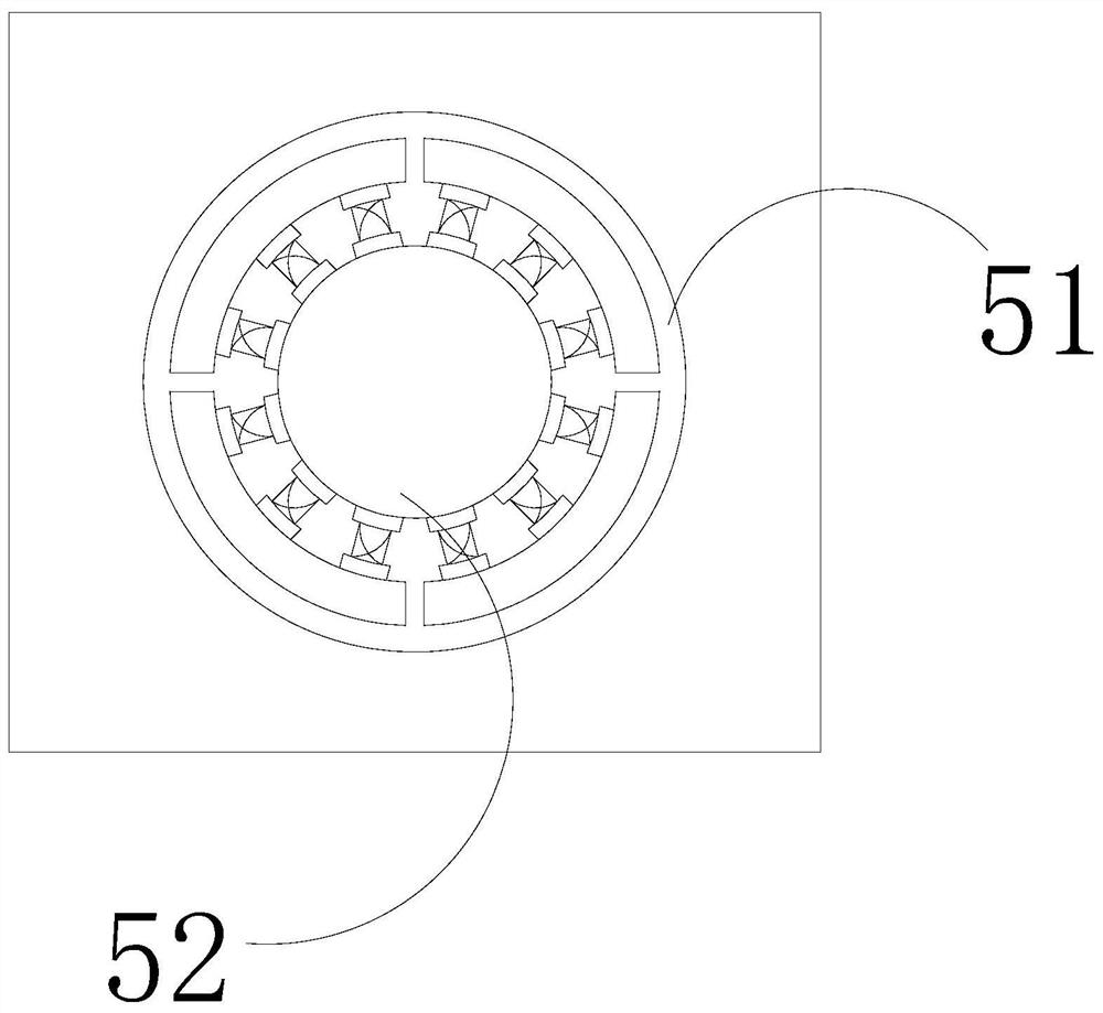
[0029] The workbench 5 is provided with a workpiece groove 51 and a clamping mechanism 52 , the workpiece groove 51 is recessed at the center of the top of the workbench 5 , and the clamping mechanism 52 is installed at the inner center of the workpiece groove 51 .

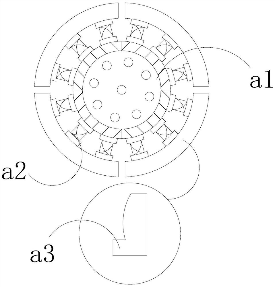
[0030] Wherein, the clamping mechanism 52 is provided with a support ring a1, a telescopic block a2, and a splint a3, the support ring a1 is located in the middle of the c...

Embodiment 2

[0036] as attached Figure 6 to attach Figure 8 Shown:

[0037] Wherein, the splint a3 is provided with a connection plate e1, a support plate e2, an inner groove e3, a push ball e4, an elastic block e5, and a contact plate e6, the connection plate e1 is located on the bottom surface of the splint a3, and the support plate e2 is connected and installed The top of the right end of the connecting plate e1, the inner groove e3 is set inside the supporting plate e2, the push ball e4 is set inside the inner groove e3, the contact plate e6 is connected to the left side of the supporting plate e2 through the elastic block e5, the There are nine push balls e4, which are evenly distributed inside the inner groove e3, which can increase the gravity of the support plate e2 and reduce the thrust swing of the support plate e2 by the workpiece. The inner groove e3 is inclined, which is conducive to pushing the ball e4 along Sliding along the inclined surface is beneficial for the support...


PUM


Abstract

The invention discloses a hydraulic machine with an automatic induction safety protection device. The hydraulic machine structurally comprises a machine body, a controller, a hydraulic cylinder, a pressing rod and a workbench, wherein the controller is arranged on the right side surface of the machine body, the hydraulic cylinder is mounted on the top of the machine body, the pressing rod is connected to the bottom of the front surface of the machine body, and the workbench is arranged below the pressing rod. When the pressing rod quickly presses a workpiece, the workpiece is prone to displacement due to the instant thrust of the pressing rod; the workpiece is clamped through a clamping mechanism and tightly sucked to the top of a supporting ring, so that position movement of the workpiece during hydraulic pressure is reduced, position dislocation of the workpiece during hydraulic pressure is reduced, and the production quality of the workpiece can be improved; the hydraulic machine generates vibrating force during operation, so that a phenomenon that the workpiece rotates in situ under vibrating force. And clamping blocks in clamping plates make contact with the outer wall of the workpiece, so that the friction force between the clamping plates and the outer wall of the workpiece is increased, the situation that the workpiece rotates in situ due to the vibrating force of the machine during machining is reduced, and hydraulic assembly of the workpiece is facilitated.

Description

technical field [0001] The invention belongs to the hydraulic field, and more specifically relates to a hydraulic machine with an automatic induction safety protection device. Background technique [0002] When assembling hardware workpieces, the hydraulic press is used to press down the workpieces, place the workpieces horizontally on the top of the workbench, and the hydraulic cylinder drives the pressure rod to move down to press down the objects. In order to reduce the displacement of the workpieces during the hydraulic process, the workbench is equipped with The workpiece groove, the workpiece is placed in the workpiece groove; when the hydraulic machine is used to hydraulically process the workpiece in the prior art, because the volume of the workpiece is different, when the hydraulic workpiece is spherical, the contact area between the bottom of the spherical workpiece and the inner wall of the workpiece groove Smaller, when the pressure rod quickly presses down on th...

Claims


Application Information

Patent Timeline
IPC IPC(8): B23P19/027
CPCB23P19/027
Inventor 刘继业
Owner 李三源
Learn More