

Novel gripper support
A new type of external surface technology, applied in the mechanical field, can solve problems such as grasping failure, complex structure, and infirmity, and achieve the effects of improving grip, improving practicability, and increasing the contact surface
- Summary
- Abstract
- Description
- Claims
- Application Information
AI Technical Summary
Problems solved by technology
Method used
Image

Examples
Embodiment Construction
[0024] The following will clearly and completely describe the technical solutions in the embodiments of the present invention with reference to the accompanying drawings in the embodiments of the present invention. Obviously, the described embodiments are only some, not all, embodiments of the present invention. Based on the embodiments of the present invention, all other embodiments obtained by persons of ordinary skill in the art without making creative efforts belong to the protection scope of the present invention.
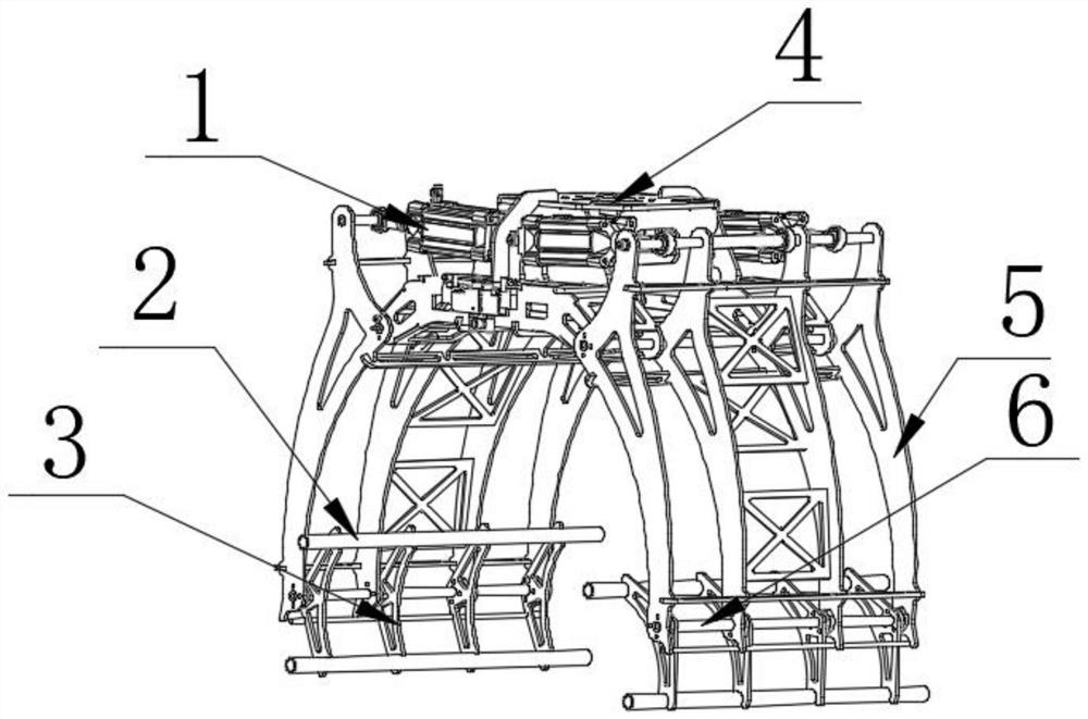
[0025] Such as Figure 1-8 As shown, the present invention provides a technical solution: a novel gripper bracket, including a power unit 4, the purpose of setting the power unit 4 is to provide kinetic energy, when the novel gripper bracket works, the power unit 4 gives the transmission mechanism 1 For energy supply, the two ends of the power unit 4 are symmetrically provided with a transmission mechanism 1, and the two ends of the transmission mechanism 1 ar...
PUM
 Abstract
Description
Claims
Application Information