High-strength low-radiation coated hollow glass for energy-saving building and preparation method of high-strength low-radiation coated hollow glass

A low-radiation coating and high-strength technology, applied in the coating and other directions, can solve the problems of hollow glass damage, low application range, glass breakage, etc., and achieve the effects of reducing shaking, protecting safety and reducing damage

Inactive Publication Date: 2021-05-25
南通大通装饰工程有限公司
10 Cites 1 Cited by

AI-Extracted Technical Summary

Problems solved by technology

[0004] 1. During the use of insulating glass, it is generally installed directly with glass materials, but in the process of use, its strength is relatively low, and the scope of application is relatively low
[0005] 2. The insulating glass has a relative length. During the installation process, relative splicing is required. Generally, it is directly fixed with fixing bolts, which is easy t...

Method used

It should be noted that the present invention is a kind of high-strength low-radiation coated hollow glass for energy-saving buildings, and the hollow glass main body 1 can be easily installed inside the protective shell 401 through the stabilizing groove 406, wherein the protective cushion 405 can effectively Protect the safety of the insulating glass main body 1, reduce the damage caused by the extrusion of the insulating glass main body 1 by the protective shell 401 and the insulating glass barrier plate 402, and the gasket 404 can facilitate the contact between the insulating glass main body 1 and the protective shell 401, and further protect the hollow glass body. The safety of the glass main body 1, wherein the spacer soft strip 403 and the stable extrusion disc 407 can effectively maintain the stability of the insulating glass main body 1, reduce the shaking of the insulating glass main body 1 inside the stable groove 406, and facilitate the use of the insulating glass main body 1 in various Such an environment further increases the strength and stability of the insulating glass main body 1 .
It should be noted that the present invention is a kind of high-strength low-radiation coated hollo...

Abstract

The invention discloses energy-saving high-strength low-radiation coated hollow glass for buildings and a preparation method of the glass. The energy-saving high-strength low-radiation coated hollow glass comprises a hollow glass body, magnetic attraction plates are arranged on the outer surfaces of the upper end and the lower end of the hollow glass body, and splicing mechanisms are arranged on the left side and the right side of the hollow glass body; high-strength mechanisms are arranged at the front end and the rear end of the hollow glass body, and a protection mechanism is arranged in the hollow glass body. The stability of the hollow glass main body can be effectively kept through the spacing soft strips and the stable extrusion wafers, shaking of the hollow glass main body in the stable grooves is reduced, the hollow glass main body can be conveniently used in various environments, the strength and stability of the hollow glass main body are further improved, and radiation layers can increase the ultraviolet absorption efficiency of the hollow glass main body, effectively block the stimulation of ultraviolet rays to personnel, further protect the safety of the personnel, reduce the occurrence of falling due to unstable splicing, and improve the use efficiency.

Application Domain

Coatings

Technology Topic

Ultraviolet absorptionStructural engineering +3

Image

  • High-strength low-radiation coated hollow glass for energy-saving building and preparation method of high-strength low-radiation coated hollow glass
  • High-strength low-radiation coated hollow glass for energy-saving building and preparation method of high-strength low-radiation coated hollow glass
  • High-strength low-radiation coated hollow glass for energy-saving building and preparation method of high-strength low-radiation coated hollow glass

Examples

  • Experimental program(4)

Example Embodiment

[0036] Specific embodiment one
[0037] This embodiment is an embodiment of a high-strength low-radiation coated insulating glass for energy-saving buildings.
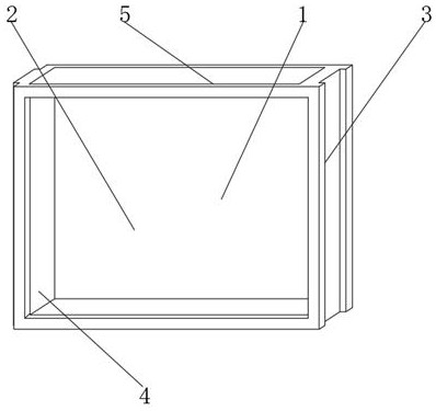
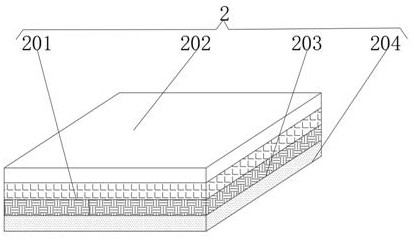
[0038] like Figure 1-2 As shown, the insulating glass body 1 is included, the outer surface of the upper and lower ends of the insulating glass body 1 is provided with a magnetic plate 5, the left and right sides of the insulating glass body 1 are provided with a splicing mechanism 3, and the front and rear ends of the insulating glass body 1 are provided with The high-strength mechanism 2 is provided with a protective mechanism 4 inside the hollow glass body 1 , and the high-strength mechanism 2 includes a high-strength layer 201 , a coating layer 202 , a radiation layer 203 and a protective layer 204 .
[0039] The insulating glass main body 1 and the high-strength mechanism 2 are integrally formed. There is a No. 1 fixing bolt between the magnetic plate 5 and the insulating glass main body 1, and the outer surfaces of the upper and lower ends of the insulating glass main body 1 are connected to the suction by the No. 1 fixing bolt. The outer wall of the magnetic plate 5 is fixedly connected, a No. 1 groove is arranged between the insulating glass body 1 and the splicing mechanism 3, and the outer surfaces of the left and right sides of the insulating glass body 1 are fixedly connected with the outer wall of the splicing mechanism 3 through the No. 1 groove, and the hollow A No. 2 groove is provided between the glass body 1 and the protective mechanism 4, and the inside of the hollow glass body 1 is fixedly connected to the outer wall of the protective mechanism 4 through the No. 2 groove; the high-strength layer 201 is located on the outer surface of the lower end of the coating layer 202, The radiation layer 203 is located on the lower outer surface of the high-strength layer 201, the protective layer 204 is located on the lower outer surface of the radiation layer 203, a No. 1 fixing glue is arranged between the high-strength layer 201 and the coating layer 202, and the upper end of the high-strength layer 201 is outside the outer surface. The surface is fixedly connected to the outer surface of the lower end of the coating layer 202 through No. 1 fixing glue, No. 2 fixing glue is arranged between the high-strength layer 201 and the radiation layer 203, and the outer surface of the lower end of the high-strength layer 201 is connected to the radiation layer through No. 2 fixing glue. The outer surface of the upper end of the layer 203 is fixedly connected, No. 3 fixing glue is arranged between the radiation layer 203 and the protective layer 204, and the outer surface of the lower end of the radiation layer 203 is fixedly connected to the upper outer surface of the protective layer 204 through the No. 3 fixing glue.
[0040] It should be noted that the present invention is a high-strength and low-radiation coated insulating glass for energy-saving buildings. The strength of the insulating glass body 1 can be increased through the high-strength layer 201, and the insulating glass body 1 can be reduced due to accidental collisions during use. , causing damage to the insulating glass body 1, and the coating layer 202 can coat the insulating glass body 1 accordingly, which can increase the effect of the insulating glass body 1, and the radiation layer 203 can increase the ultraviolet absorption efficiency of the insulating glass body 1, effectively blocking ultraviolet rays The stimulation to personnel further protects the safety of personnel, wherein the material of radiation layer 203 is composite ultraviolet absorber, the material of protective layer 204 is glass fiber, and the material of high-strength layer 201 is plastic fiber material.

Example Embodiment

[0041] Specific embodiment two
[0042] This embodiment is an embodiment of a splicing structure in high-strength low-radiation coated insulating glass for energy-saving buildings.
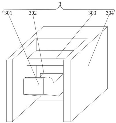
[0043] like figure 1 , 3 , 4, the splicing mechanism 3 includes a buckle assembly 301, a splicing groove 302, a soft buffer block 303, a splicing frame 304 and an extruding spring 305, and the outer surface of the front end of the splicing frame 304 is provided with a splicing groove 302, and the snap assembly 301 is located inside the splicing groove 302, the buffer soft block 303 is located on the outer surface of the front end of the splicing frame 304 and is located at the upper end of the splicing groove 302, and the pressing spring 305 is located inside the splicing groove 302 and is located at the rear end of the buckle assembly 301 The outer surface.
[0044] No. 1 superglue is arranged between the buffer soft block 303 and the splicing frame 304, and the rear end outer surface of the buffer soft block 303 is fixedly connected with the front end outer surface of the splicing frame 304 through No. 1 super glue, and the extrusion spring 305 is connected to the splicing frame 304 Four good fixing glues are arranged between them, and the inside of the front end of the splicing frame 304 is fixedly connected with the rear end outer surface of the extrusion spring 305 through the No. No. 5 fixing glue is provided, and the outer surface of the front end of the extrusion spring 305 is fixedly connected with the rear end outer surface of the buckle assembly 301 through the No. 5 fixing glue. It is movably connected with the outer surface of the front end of the splicing frame 304 .
[0045] It should be noted that the present invention is a high-strength and low-emissivity coated insulating glass for energy-saving buildings. When the insulating glass main body 1 needs to be used, the staff can facilitate the two relative fittings through the card slot, and the buffer soft block 303 can It plays the role of cushioning and protection, and can further improve the stability of the splicing process of the insulating glass body 1. Afterwards, under the action of the extrusion spring 305, the buckle component 301 can facilitate the buckle component 301 to enter the interior of the insulating glass body 1, thereby maintaining The stability of the two hollow glass bodies 1 reduces the occurrence of falling off due to unstable splicing, and improves the use efficiency.

Example Embodiment

[0046] Specific embodiment three
[0047] This embodiment is an embodiment of a protective structure in a high-strength low-radiation coated hollow glass for energy-saving buildings.
[0048] like figure 1 , 5 As shown, the protective mechanism 4 includes a protective shell 401, a hollow glass blocking plate 402, a soft spacer strip 403, a sealing pad 404, a protective soft pad 405, a stable groove 406, a stable extrusion disc 407 and an extrusion circular groove 408, sealing The pad 404 is located on the outer surface of the front end of the protective shell 401, the spacer soft strip 403 is located on the outer surface of the front end of the gasket 404, the insulating glass blocking plate 402 is located on the outer surface of the front end of the protective shell 401 and runs through the wall of the sealing gasket 404, and the insulating glass blocking plate 402 is located at the upper and lower ends of the spacer soft strip 403, and the inner surface of the upper and lower ends of the protective shell 401 is provided with an extruded circular groove 408, and the stable extruded disc 407 is located inside the extruded circular groove 408 and extends to the outside of the protective shell 401. A stabilizing groove 406 is defined between the protective shell 401 and the insulating glass blocking plate 402 , and the protective cushion 405 is located on the inner surface of one side of the stabilizing groove 406 .
[0049] The insulating glass blocking plate 402 is connected to the protective shell 401 by welding, No. 2 superglue is set between the protective cushion 405 and the stabilizing groove 406, and the outer wall of the protective cushion 405 is connected to the stabilizing groove 406 by No. 2 fixing glue. No. 3 super glue is set between the gasket 404 and the protective shell 401, and the outer surface of the rear end of the gasket 404 is fixedly connected with the front outer surface of the protective shell 401 through No. 3 super glue, and the spacer soft strip 403 and No. 4 superglue is arranged between the gaskets 404, and the outer surface of the rear end of the spacer soft strip 403 is fixedly connected to the outer surface of the front end of the gasket 404 through No. 4 superglue to firmly squeeze the space between the disc 407 and the protective shell 401. No. 5 superglue is provided, and the outer wall of the firmly extruded disc 407 is fixedly connected with the inner surfaces of the upper and lower ends of the protective shell 401 through No. 5 superglue and the extruded circular groove 408 .
[0050] It should be noted that the present invention is a high-strength low-radiation coated insulating glass for energy-saving buildings. The insulating glass main body 1 can be easily installed inside the protective shell 401 through the stabilizing groove 406, and the protective cushion 405 can effectively protect the insulating glass. The safety of the main body 1 reduces the damage caused by the extrusion of the insulating glass main body 1 by the protective shell 401 and the insulating glass blocking plate 402, and the gasket 404 can facilitate the contact between the insulating glass main body 1 and the protective shell 401, further protecting the insulating glass main body 1 safety, wherein the spacer soft strip 403 and the stable extrusion disc 407 can effectively maintain the stability of the insulating glass body 1, reduce the shaking of the insulating glass body 1 inside the stable groove 406, and facilitate the use of the insulating glass body 1 in various environments. The strength and stability of the hollow glass main body 1 are further increased.

PUM

no PUM

Description & Claims & Application Information

We can also present the details of the Description, Claims and Application information to help users get a comprehensive understanding of the technical details of the patent, such as background art, summary of invention, brief description of drawings, description of embodiments, and other original content. On the other hand, users can also determine the specific scope of protection of the technology through the list of claims; as well as understand the changes in the life cycle of the technology with the presentation of the patent timeline. Login to view more.

Similar technology patents

Electrolytic copper foil drying device

Owner:GUANGDONG FINE YUAN SCI TECH CO LTD

Material pulverizing and sieving device

Owner:CHENZHOU JINTONG INFORMATION TECH CO LTD

Equipment and method for mapping variable sub carriers

InactiveCN1917418AImprove the effectImprove the probability of HARQ transmission failure
Owner:BEIJING SAMSUNG TELECOM R&D CENT +1

Classification and recommendation of technical efficacy words

  • Improve the effect

Liquid blast furnace slag granulation method and device thereof

InactiveCN101665845AIncrease impactImprove the effect
Owner:TSINGHUA UNIV +1

Real-time subtitle display method and system

ActiveCN106331893Aimprove intelligibilityImprove the effect
Owner:IFLYTEK CO LTD

Calculation method for electric quantities of battery, device and terminal

InactiveCN102508172AImproved power calculation accuracyImprove the effect
Owner:ZTE CORP

Information reminding method and device

ActiveCN104618218AImprove the effect
Owner:GUANGZHOU KUGOU TECH
Why Eureka
Try Eureka