Roadbed widening structure under steep terrain condition and construction method thereof

A technology based on topography and conditions, applied in the direction of basic structure engineering, underwater structures, roads, etc., can solve the problems that excavation and retaining structures are difficult to meet engineering needs, the number of foam concrete projects is large, and foam concrete is easy to crack. Achieve the effects of reducing construction difficulty and construction risk, improving anti-slip ability, and reducing the volume of dock workers

Pending Publication Date: 2021-05-25
ZHEJIANG COMM CONSTR GRP CO LTD
View PDF3 Cites 0 Cited by
  • Summary
  • Abstract
  • Description
  • Claims
  • Application Information

AI Technical Summary

Problems solved by technology

Due to the large requirement for the bottom width of foam concrete, it will inevitably lead to a large number of foam concrete projects, high cost, and the disadvantages of foam concrete such as easy cracking. In summary, for some mountainous road reconstruction and expansion projects with small investment and tight funds There are certain limitations in the application and promotion of qualitative composite components
[0006] Considering the widening and rebuilding of existing mountain roads under steep terrain conditions, conventional excavation and retaining structures are difficult to meet engineering needs, or the existing technical work costs are high. Therefore, the present invention proposes a stable and safe road under steep terrain conditions. , Low engineering cost, low construction difficulty and low construction risk, and the subgrade widening technology and construction method that meet the requirements of highway traffic protection have important engineering significance and practical value, and can be used for the design and construction of roadbed widening in mountainous areas under steep terrain conditions. Construction provides a certain reference

Method used


Image

  • Roadbed widening structure under steep terrain condition and construction method thereof
  • Roadbed widening structure under steep terrain condition and construction method thereof
  • Roadbed widening structure under steep terrain condition and construction method thereof

Examples


Embodiment

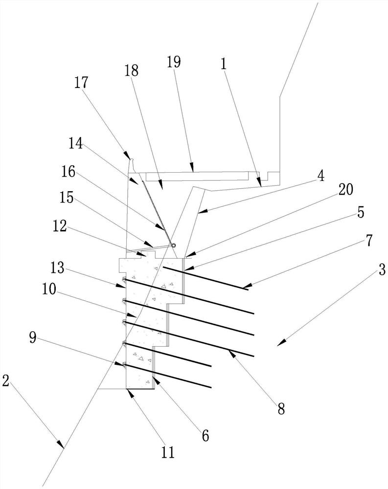
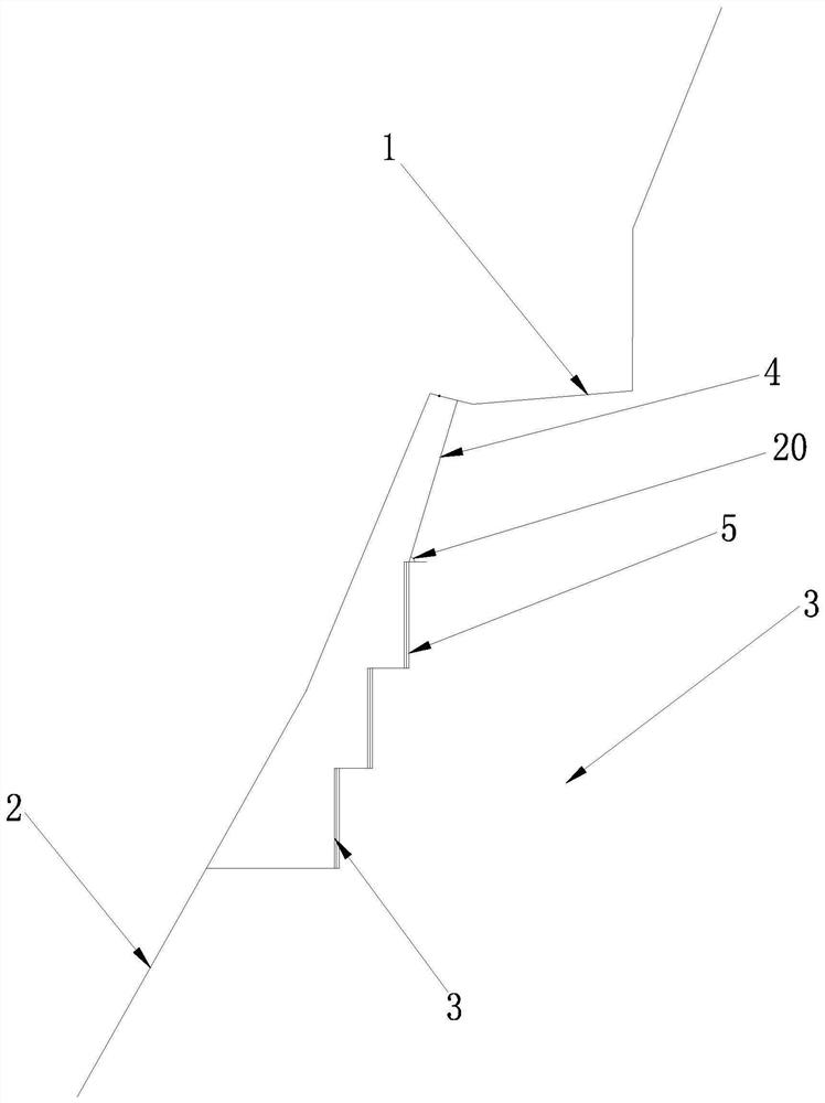
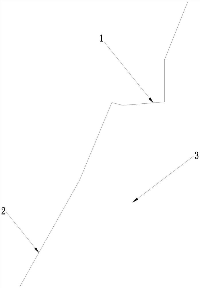
[0035] Such as Figure 1-3 As shown, the roadbed widening structure provided by this embodiment includes a mountain body 3, and the mountain body 3 includes an old road 1 and a steep wall 2 located on the valley side of the old road 1, and the steep wall 2 on the valley side is excavated inward to form a wall Excavate the side wall 4 and the stepped artificial steep wall 5 after excavation; the stepped artificial steep wall 5 is provided with anchoring steel bars 7 and multiple anchor rods 8 of different heights, and the anchoring steel bars 7 and anchor rods 8 are anchored inward along the stepped artificial steep wall 5 The mountain body 3; the outer side of the stepped artificial steep wall 5 is provided with a concrete step foundation 10; the top of the step foundation is provided with a step foundation tenon 12 and is connected with the retaining wall 14 as a whole; the backfill filler 18 is compacted behind the retaining wall 14 After that, it is spliced ​​with the old r...


PUM


Abstract

The invention relates to a roadbed widening structure under a steep terrain condition and a construction method thereof. The structure comprises a mountain body, the mountain body comprises an old road and a free steep wall located on the valley side of the old road, and after the steep wall is excavated inwards to form a wall, a side wall and a step-shaped artificial steep wall are excavated; the step-shaped artificial steep wall is provided with anchoring steel bars and a plurality of anchor rods with different heights, and the anchoring steel bars and the anchor rods are anchored into the mountain body inwards along the step-shaped artificial steep wall. The structure and method have the advantages of being safe, stable, small in excavation work amount, small in dock work size, low in manufacturing cost, convenient to construct and free of influence on old road passing, solves the problems that the conventional excavation work amount is large or a retaining structure is high in manufacturing cost and cannot keep passing, and construction difficulty and construction risks are reduced. And a certain reference function can be provided for the design and construction of widening the highway subgrade in the mountainous area under the steep terrain condition.

Description

technical field [0001] The invention belongs to the technical field of road widening, and in particular relates to a roadbed widening structure under steep terrain conditions and a construction method thereof. Background technique [0002] At present, in order to adapt to the rapid growth of traffic volume, there are more and more roadbed widening and reconstruction projects in mountainous areas. When widening and rebuilding existing mountain roads under steep terrain conditions, often due to terrain constraints, if the road is widened near the top of the mountain, the amount of excavation will be huge. On the one hand, the road needs to be closed during excavation, and the road cannot be guaranteed. On the other hand, large-scale excavation of the mountain will put forward higher requirements for slope stability and environmental protection; if it is widened along the bottom of the valley, the existing retaining structure will have a large amount of roadbed excavation, a la...

Claims


Application Information

Patent Timeline
Patent Type & Authority Applications(China)
IPC IPC(8): E01C3/00E02D29/02E02D5/74
CPCE01C3/00E02D5/74E02D29/02
Inventor 涂杰文缪建冬封懿林宇程
Owner ZHEJIANG COMM CONSTR GRP CO LTD
Why Eureka
Try Eureka