Quantitative pressure suction valve

A valve body and air pressure technology, used in control valves, valve devices, valve details, etc., can solve problems such as physical impact, home decoration loss, air and water pollution, etc., to reduce odor, eliminate pollution, and save material costs.

Active Publication Date: 2021-05-25
江苏江澜实业有限公司
View PDF8 Cites 10 Cited by
  • Summary
  • Abstract
  • Description
  • Claims
  • Application Information

AI Technical Summary

Problems solved by technology

[0003] 1. Many plastic parts such as water tanks and floating balls need to be used, and the material cost is relatively high;
[0004] 2. The congenital air leakage and water sinking defect of the floating ball has not been resolved;
[0005] 3. A large number of rubber hoses used inside have obvious odor phenomenon at high temperature, which has a certain impact on the body;
[0006] 4. The pipeline machine cannot be tilted, and the water flow will not stop if the m

Method used


Image

  • Quantitative pressure suction valve
  • Quantitative pressure suction valve
  • Quantitative pressure suction valve

Examples


Embodiment 1

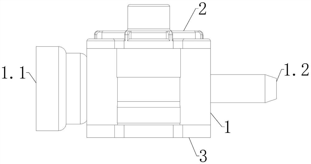
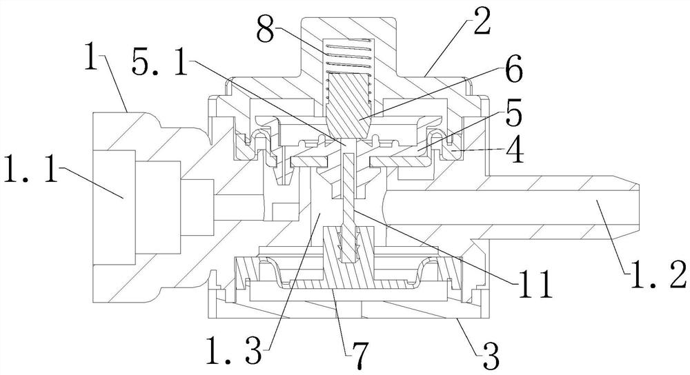
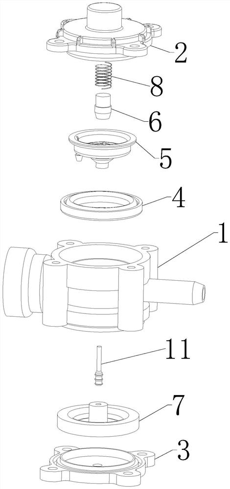
[0034] Embodiment one: if figure 1 — Figure 4 As shown, the quantitative suction valve includes a valve body 1, the top and bottom of the valve body 1 are respectively equipped with an upper cover 2 and a lower cover 3, and the left and right sides of the valve body 1 have a water inlet 1.1 and a suction water outlet 1.2 respectively. The upper end of 1 is fixed with a hydraulic pressure diaphragm 5 through a support frame 4, the outer edge of the support frame 4 is stuck between the upper end of the valve body 1 and the lower end of the upper cover 2, the hydraulic diaphragm 5 is connected to the water inlet 1.1, and the water pressure The center of the diaphragm 5 has a central diversion hole 5.1 that communicates with the suction outlet 1.2;

[0035] The top of the hydraulic diaphragm 5 is pressed with a sealing column 6 for blocking the central diversion hole 5.1, the upper cover 2 is equipped with a pressing piece for pressing the sealing column 6 downward, and the lowe...

Embodiment 2

[0042] Embodiment two: if Figure 5 As shown, the difference between Embodiment 2 and Embodiment 1 is that the lower pressing member is composed of a first magnet 9 and a second magnet 10, the first magnet 9 is fixed in the upper cover 2, and the second magnet 10 is fixed on the upper end of the sealing column 6 , the first magnet 9 is located above the second magnet 10 and repels the second magnet 10 , and the outer wall of the sealing column 6 is in contact with the inner wall of the upper cover 2 . The sealing column 6 can tightly block the upper end of the central diversion hole 5.1 through the repulsive force between the first magnet 9 and the second magnet 10 .

Embodiment 3

[0043] Embodiment three: as Image 6 As shown, the difference between the third embodiment and the first embodiment is that the top piece is installed between the air pressure diaphragm 7 and the sealing column 6, the top piece is composed of the third magnet 12 and the fourth magnet 13, and the third magnet 12 is fixed At the bottom of the sealing column 6 and extending into the center diversion hole 5.1, there is a gap for water to pass between the third magnet 12 and the inner wall of the center diversion hole 5.1, the fourth magnet 13 is fixed on the upper end of the air pressure diaphragm 7, and the fourth The magnet 13 is located below the third magnet 12 and repels the third magnet 12. When the fourth magnet 13 moves upward, the third magnet 12 is driven by the repulsive force of the fourth magnet 13 to move the sealing column 6 upward, so that the central guide hole 5.1 The upper end is opened.


PUM


Abstract

The invention discloses a quantitative pressure suction valve which comprises a valve body. A water inlet and a water suction outlet are formed in the two sides of the valve body, a water pressure diaphragm piece is fixed in the upper end of the valve body, and a center flow guide hole is formed in the center of the water pressure diaphragm piece. A sealing column used for blocking the center flow guide hole is pressed at the top of the water pressure diaphragm piece, a downward pressing piece used for pressing the sealing column downwards is installed in an upper cover, an air pressure diaphragm piece is installed in the lower end of the valve body, and an upward ejecting piece used for ejecting the sealing column upwards is installed at the upper end of the air pressure diaphragm piece or between the air pressure diaphragm piece and the sealing column. According to the quantitative pressure suction valve, use of multiple plastic parts such as a water tank and a floating ball is eliminated, and a large amount of material cost can be saved for enterprises and the country; no floating ball is used, and the problems of the defects of congenital air leakage, water inflow and sinking of floating balls are solved; use of a large part of rubber pipes can be reduced, and peculiar smells can be obviously reduced; the quantitative pressure suction valve can rotate by 360 degrees in all directions and do not leak water; the quantitative pressure suction valve can be suitable for various RO reverse osmosis machine types; and pollution caused by long-time contact of water and air can be eradicated.

Description

technical field [0001] The invention relates to a valve, in particular to a quantitative suction pressure valve. Background technique [0002] The valve is a pipeline accessory used to open and close the pipeline, control the flow direction, adjust and control the parameters of the conveying medium. In the wading industry, the internal structure of the traditional pipeline machine has the following defects: [0003] 1. Many plastic parts such as water tanks and floating balls need to be used, and the material cost is relatively high; [0004] 2. The congenital air leakage and water sinking defect of the floating ball has not been resolved; [0005] 3. A large number of rubber hoses used inside have obvious odor phenomenon at high temperature, which has a certain impact on the body; [0006] 4. The pipeline machine cannot be tilted, and the water flow will not stop if the micro-ultrasonic machine is tilted a little bit, which will cause great losses to home decoration; ...

Claims


Application Information

Patent Timeline
IPC IPC(8): F16K15/18F16K15/02F16K27/02F16K31/08F16K31/126
CPCF16K15/18F16K15/02F16K15/025F16K27/0209F16K31/084F16K31/1266
Inventor 季前
Owner 江苏江澜实业有限公司
Why Eureka
Try Eureka