Arc uniform-temperature loop heat tube with variable upstream angle

A loop heat pipe and evaporating tube technology, which is applied in the field of loop heat pipes, can solve the problems of uneven heat absorption of heat utilization components, overheating of heat utilization components, and different heat dissipation in the condensing section, so as to achieve the effect of excellent outlet fluid temperature uniformity and avoid flow Increased resistance, avoiding the effect of uneven mixing

Inactive Publication Date: 2021-05-25
青岛乾福圣耀商贸有限公司 +1
View PDF12 Cites 2 Cited by
  • Summary
  • Abstract
  • Description
  • Claims
  • Application Information

AI Technical Summary

Problems solved by technology

[0005] During the flow of the fluid in the evaporating tube, generally the evaporating tube is a vapor-liquid two-phase flow dominated by steam, so that the fluid in the evaporating tube is a vapor-liquid mixture, The existence of vapor-liquid two-phase flow affects the heat absorption efficiency of the evaporator tube
[0006] In the research, it was found that whether it is the heat absorption at the endothermic end or the heat preservation of the evaporator tube, the temperature of the fluid at different positions of the evaporator tube is not uniform, such as adiabatic The side with a good effect has a high temperature, and the position with a poor heat insulation effect has a low temperature, which causes the temperature of the fluid in different positions inside the evaporator tube to be different, because the temperature difference will cause the temperature in the evaporator tube to be uneven. The heat dissipation of the condensation section in different positions is different, especially when multiple heat release ends and corresponding heat utilization components are involved. The heat absorption of heat utilization components caused by different heat dissipation ends is uneven, resulting in overheating or overcooling of heat utilization components. , which affects the operation of
In the case of multiple heat-absorbing ends, different heat sources at the heat-absorbing ends lead to different fluid temperatures in different positions of the heat pipe condensing part, resulting in overheating or overcooling of heat utilization components, which affects operation
[0007] In response to the above problems, the applicant's prior patent application provides a new loop heat pipe, so as to solve the problem of uneven temperature of the fluid inside the heat pipe

Method used


Image

  • Arc uniform-temperature loop heat tube with variable upstream angle
  • Arc uniform-temperature loop heat tube with variable upstream angle
  • Arc uniform-temperature loop heat tube with variable upstream angle

Examples


Embodiment Construction

[0035] The specific embodiments of the present invention will be described in detail below in conjunction with the accompanying drawings.

[0036] In this article, if there is no special explanation, when it comes to formulas, " / " means division, and "×" and "*" mean multiplication.

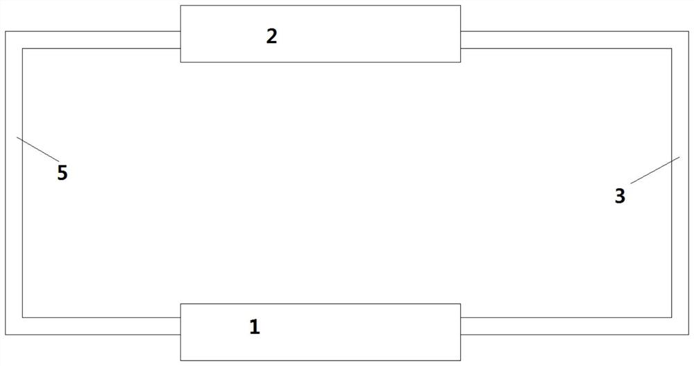
[0037] figure 1 A heat pipe is shown. like figure 1 As shown, the loop heat pipe includes an evaporating part 1, a condensing part 2, an evaporating pipe 3 and a condensing pipe 5. The liquid absorbs heat and evaporates in the evaporating part 1, enters the condensing part 2 through the evaporating pipe 3 to release heat, and then condenses The pipe 5 returns to the evaporation section 1 .

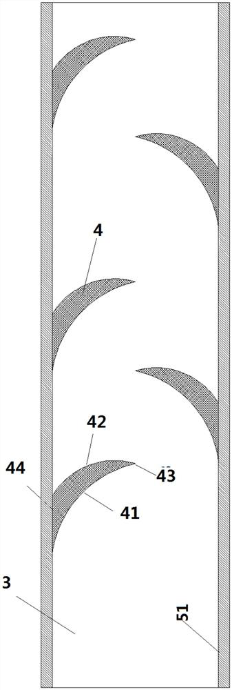
[0038] Preferably, an insulating layer is provided outside the evaporation tube 3 .

[0039] Preferably, the inner wall of the condensation pipe 5 is provided with a capillary structure. By setting the capillary structure, the liquid is promoted to enter the evaporation part as soon as possible.

[00...


PUM


Abstract

The invention provides a loop heat tube which comprises an evaporation part, a condensation part, an evaporation tube and a condensation tube, wherein liquid absorbs heat and evaporates at the evaporation part, enters the condensation part through the evaporation tube to release heat, and then returns to the evaporation part through the condensation tube; a plurality of uniform-temperature components are arranged on the inner wall of the evaporation tube in the flowing direction of the steam, and the downstream angle becomes smaller and smaller in the flowing direction of the steam. According to the novel loop heat tube provided by the invention, the downstream included angle is set to be smaller and smaller, so that the flow resistance is reduced, and the temperature equalizing effect achieves the basically same effect on the aspects of resistance reduction and material cost saving.

Description

technical field [0001] The invention relates to a loop heat pipe, in particular to a loop heat pipe provided with a temperature uniform component. Background technique [0002] Heat pipe technology was developed in Los Alamos, USA in 1963. national laboratory A heat transfer method called a "heat pipe" invented by George Grover element , it makes full use of the principle of heat conduction and the rapid heat transfer properties of phase change media, and quickly transfers the heat of the heating object to the heat source through the heat pipe, and its thermal conductivity exceeds that of any known metal. [0003] Heat pipe technology was widely used in aerospace, military and other industries before. Since it was introduced into the radiator manufacturing industry, people have changed the traditional radiator design ideas and got rid of the single heat dissipation mode that only relies on high air volume motors to obtain better heat dissipation. The use of heat pipe tech...

Claims


Application Information

Patent Timeline
Patent Type & Authority Applications(China)
IPC IPC(8): F28D15/02
CPCF28D15/0266
Inventor 不公告发明人
Owner 青岛乾福圣耀商贸有限公司
Why Eureka
Try Eureka