Eureka AIR delivers breakthrough ideas for toughest innovation challenges, trusted by R&D personnel around the world.

Tail gas filtering device and coating equipment

A technology of exhaust gas filtration and coating equipment, which is applied in the direction of gaseous chemical plating, dispersed particle filtration, membrane technology, etc., and can solve problems such as vacuum pump alarms, reduced production efficiency, and large pressure drop

Pending Publication Date: 2021-05-28
JIANGSU FAVORED NANOTECHNOLOGY CO LTD
View PDF9 Cites 1 Cited by
  • Summary
  • Abstract
  • Description
  • Claims
  • Application Information

AI Technical Summary

Problems solved by technology

[0005] In the actual use process, it is found that there are still two problems in filtering with filter bottles. One problem is that the production efficiency is reduced due to shutdown. The service life of a filter bottle is about one week, which means that it needs to be shut down once a week. The problem is that the gas flow diameter of the filter bottle is small and the pressure drop is large, which causes the vacuum pump with small back pressure requirements to often alarm

Method used


Image

  • Tail gas filtering device and coating equipment
  • Tail gas filtering device and coating equipment
  • Tail gas filtering device and coating equipment

Examples


Embodiment Construction

[0039] The following description serves to disclose the present invention to enable those skilled in the art to carry out the present invention. The preferred embodiments described below are only examples, and those skilled in the art can devise other obvious variations. The basic principles of the present invention defined in the following description can be applied to other embodiments, variations, improvements, equivalents and other technical solutions without departing from the spirit and scope of the present invention.

[0040] Those skilled in the art should understand that in the disclosure of the present invention, the terms "vertical", "transverse", "upper", "lower", "front", "rear", "left", "right", " The orientation or positional relationship indicated by "vertical", "horizontal", "top", "bottom", "inner", "outer", etc. is based on the orientation or positional relationship shown in the drawings, which are only for the convenience of describing the present invention...


PUM


Abstract

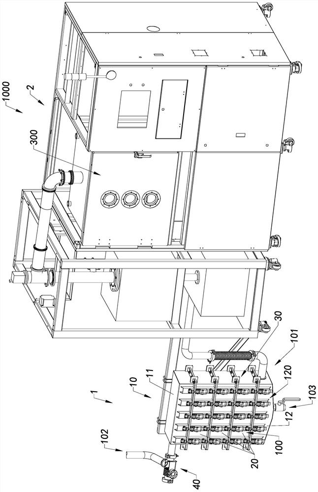
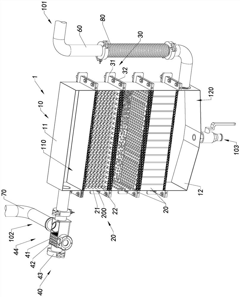
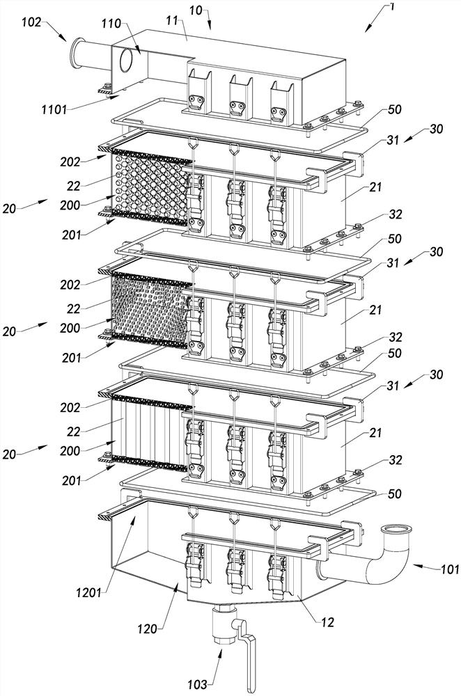
The invention provides a tail gas filtering device and coating equipment. The tail gas filtering device comprises at least one filtering unit, a first mounting unit and a second mounting unit, and the filtering unit is convenient to replace and can be replaced in time.

Description

technical field [0001] The invention relates to the field of tail gas treatment, in particular to a tail gas filtering device and coating equipment. Background technique [0002] During the coating process, the reaction raw materials are fed into the reaction chamber for reaction, and part of the unreacted raw materials and part of the by-products generated by the reaction will form tail gas and need to be discharged from the reaction chamber in time to make the pressure of the reaction chamber Within the control range, these exhaust gases are usually harmful to the environment if they are directly discharged. [0003] The exhaust gas is usually absorbed by setting a filter bottle at the outlet position. Filter material is placed in the filter bottle, and when the tail gas treatment capacity of the filter bottle reaches the upper limit, it is replaced with a new filter bottle. For a coating equipment, the reaction chamber of the coating equipment needs to be maintained at ...

Claims


Application Information

Patent Timeline
Patent Type & Authority Applications(China)
IPC IPC(8): B01D53/00B01D53/02B01D46/00B01D46/30C23C16/44
CPCB01D53/00B01D53/02B01D46/30C23C16/44B01D2258/025B01D46/62B01D46/0013C23C16/4412B01D46/0005B01D46/0086B01D2271/02
Inventor 宗坚王志军
Owner JIANGSU FAVORED NANOTECHNOLOGY CO LTD
Why Eureka
Eureka Blog
Learn More