
Continuous bending machining machine for steel structure sectional materials

A technology for processing machinery and steel structures, applied in the field of steel processing, can solve the problems of unbalanced force on the pressure roller, affecting the service life of the pressure roller, damage, etc., and achieve the effect of convenient cleaning

Inactive Publication Date: 2021-05-28
闫国亚
View PDF9 Cites 3 Cited by
  • Summary
  • Abstract
  • Description
  • Claims
  • Application Information

AI Technical Summary

Problems solved by technology

[0003] During the bending process of T-shaped steel, the position of T-shaped steel is often guided and restricted by the joint action of pressure roller and supporting roller, but the residual dirt on the horizontal section of T-shaped steel is easy to accumulate on the pressure roller, causing the pressure roller to Unbalanced and damaged, affecting the service life of the pressure roller

Method used


Image

  • Continuous bending machining machine for steel structure sectional materials
  • Continuous bending machining machine for steel structure sectional materials
  • Continuous bending machining machine for steel structure sectional materials

Examples


specific Embodiment approach

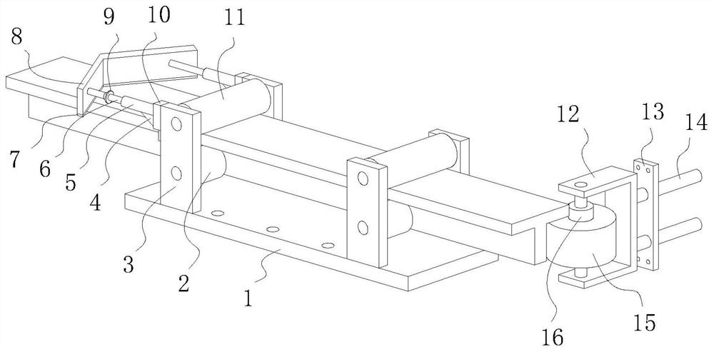
[0039] The specific embodiment: the V-shaped plate 8 in contact with the T-shaped steel horizontal section is set at the feed side of the pressure roller 11, and then when the T-shaped steel moves under the drive of the drive equipment, the V-shaped plate 8 is on the T-shaped steel surface relative to the T-shaped steel. Sliding, so that the dirt on the upper surface of the T-shaped steel horizontal section is pushed down by the V-shaped plate 8, which realizes convenient cleaning of the remaining dirt on the upper surface of the T-shaped steel horizontal section, and prevents the dirt from accumulating on the pressure roller 11 and affecting the use of the pressure roller 11 life.

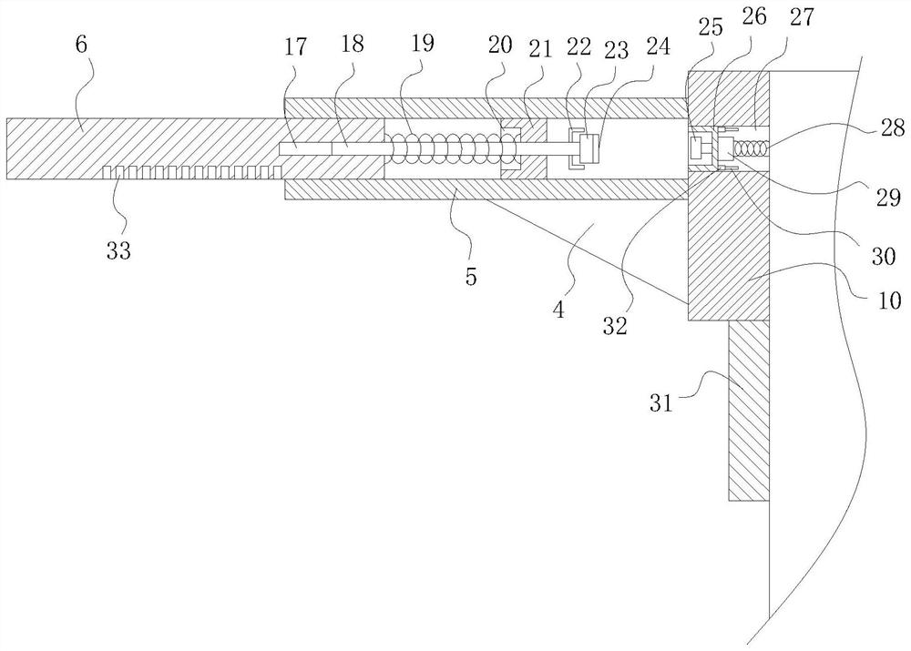
[0040] After inserting the plunger 6 into the sleeve 5, when there are hard objects such as welding slag on the upper surface of the T-shaped steel horizontal section, the protruding hard objects cannot pass under the V-shaped plate 8, so the V-shaped plate 8 follows the The T-shaped steel moves, ...


PUM


Abstract

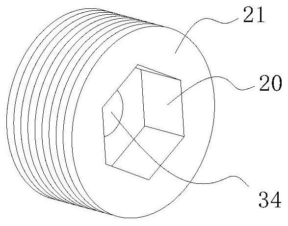
The invention relates to the technical field of steel machining, and specifically relates to a continuous bending machining machine for steel structure sectional materials. The continuous bending machining machine comprises a base, two pressing rollers used for pressing T-shaped steel are arranged on the upper side of the base, and a V-shaped plate used for removing sundries on the surface of the T-shaped steel is arranged on the feeding sides of the pressing rollers. Two horizontally-arranged inserting rods are symmetrically installed on the inner surface of the V-shaped plate, the end, away from the V-shaped plate, of each inserting rod is sleeved with a sleeve, the end, away from the corresponding inserting rod, of each sleeve is fixedly connected with a protruding block, and the position, provided with an internal threads, of each sleeve is in threaded connection with an external thread disc. A pin hole communicating with an inner hexagonal hole is formed in the face, away from the corresponding inserting rod, of each outer threaded disc, a pressing rod is inserted in each pin hole, and each pressing rod is sleeved with a reset spring. Compared with the prior art, the continuous bending machining machine has the following beneficial effects that dirt left on the upper surface of the horizontal section of the T-shaped steel is conveniently and rapidly removed, and the situation that due to the fact that the dirt is accumulated at the positions of the pressing rollers, the service life of the pressing rollers is influenced is prevented.

Description

technical field [0001] The invention relates to a continuous bending machine for steel structure profiles, which belongs to the technical field of steel processing. Background technique [0002] Steel structures are generally made of profiles, among which T-shaped steel is a type of profile. T-shaped steel is named because its cross-section is the same as the English letter "T". There are two types of T-shaped steel: one is directly cut with H-shaped steel. Divided into T-shaped steel, it is an ideal material to replace double-angle steel welding. It has the advantages of strong bending resistance, simple construction, cost saving and light structure weight. The other is hot-rolled one-time forming T-shaped steel, which is mainly used in machinery and small hardware filling steel, etc. When the T-shaped steel is used for special parts, it needs to be bent to make the T-shaped steel form a certain arc. [0003] During the bending process of T-shaped steel, the position of T...

Claims


Application Information

Patent Timeline
Patent Type & Authority Applications(China)
IPC IPC(8): B21D7/06B21D7/16B08B1/02B08B1/20
CPCB21D7/06B21D7/16B08B1/20
Inventor 闫国亚黄伟伟
Owner 闫国亚
Learn More