
Numerical control clamp system used for numerical control machine tool and using method of numerical control clamp system

A technology of CNC machine tool and fixture system, which is applied in the direction of clamping, manufacturing tools, metal processing machinery parts, etc., and can solve the problem of not being able to meet the requirements of inner hole clamping.

Inactive Publication Date: 2021-05-28
浙江赫科智能装备有限公司
View PDF9 Cites 5 Cited by
  • Summary
  • Abstract
  • Description
  • Claims
  • Application Information

AI Technical Summary

Problems solved by technology

[0003] In the CNC machining of existing workpieces, it is often necessary to clamp the inner hole of the large tubular workpiece to facilitate the rapid processing of the large tubular workpiece, but there is no CNC fixture for the inner hole clamping that can meet the requirements.

Method used


Image

  • Numerical control clamp system used for numerical control machine tool and using method of numerical control clamp system
  • Numerical control clamp system used for numerical control machine tool and using method of numerical control clamp system
  • Numerical control clamp system used for numerical control machine tool and using method of numerical control clamp system

Examples


Embodiment 1

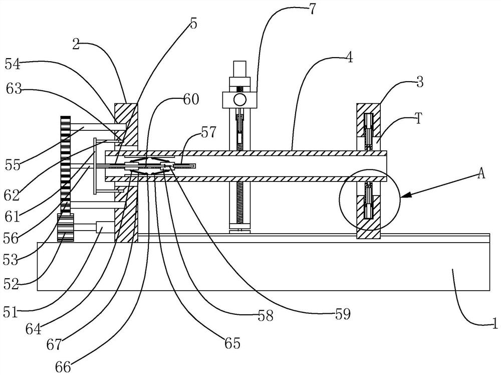
[0030]The invention discloses a numerically controlled fixture system for numerically controlled machine tools, comprising a numerically controlled machine tool platform 1, a first support plate 2 fixedly installed on the numerically controlled machine tool platform 1, movably installed on the numerically controlled machine tool platform 1 and connected with the first support plate 2. The second support plate 3 arranged in parallel. The first support plate 2 and the second support plate 3 are provided with a through hole T, and a tubular workpiece 4 is erected between the two through holes T. In the specific embodiment of the present invention In 1, an inner hole clamping device 5 for clamping a tubular workpiece 4 is installed on the CNC machine tool platform 1, and the inner hole clamping mechanism 5 includes an inner hole clamping device installed on the first support plate 2 and the output end is horizontally arranged. The first servo motor 51, the first driving gear 52 fix...

Embodiment 2

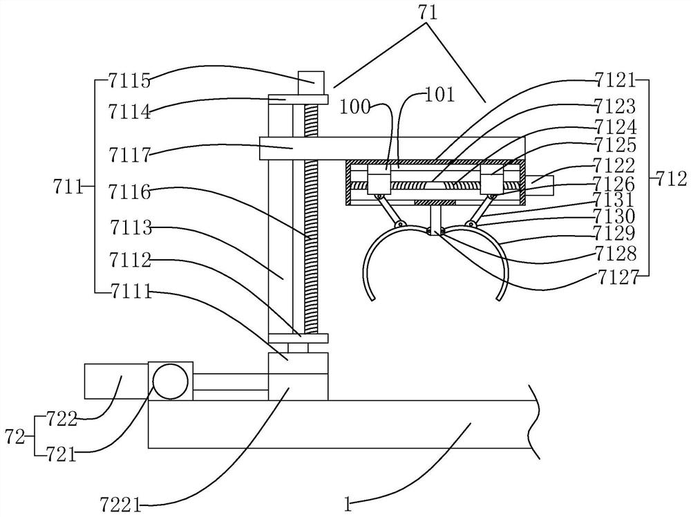
[0034] In Embodiment 2 of the present invention, the CNC machine tool platform 1 is provided with a loading and unloading device 7 for loading the tubular workpiece 4 into the through holes T of the first support plate 2 and the second support plate 3. The device 7 includes a workpiece clamping mechanism 71 and a displacement mechanism 72 that drives the workpiece clamping mechanism 71 to move, and the displacement mechanism 72 includes a horizontal horizontal driving electric cylinder 721 installed on the platform 1 of the CNC machine tool and connected to the horizontal horizontal Drive the electric cylinder 721 to drive and connect the horizontal and vertical driving electric cylinder 722, the horizontal and longitudinal driving electric cylinder 721 is used to drive the horizontal and longitudinal driving electric cylinder 722 to reciprocate along the horizontal horizontal direction, the output of the horizontal and longitudinal driving electric cylinder 722 A base plate 72...

Embodiment 3

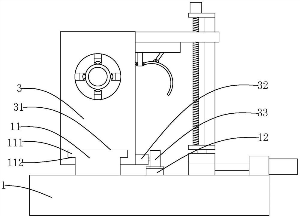
[0041] In Embodiment 3 of the present invention, the CNC machine tool platform 1 is provided with a linear guide rail 11 extending toward the first support plate 2, the second support plate 3 is slidably arranged on the linear guide rail 11, and the second support The plate 3 is provided with a through groove 31 which can be partially embedded into the linear guide rail 11. One side of the linear guide rail 11 is provided with a toothed linear guide rail 12 parallel to it and fixedly installed on the CNC machine platform 1. The second support A fifth servo motor 32 is fixedly installed on the side wall near the bottom of the plate 3, and the output end of the fifth servo motor 32 is fixedly sleeved with a second driving gear 33, and the second driving gear 33 and the toothed linear guide rail 12 tooth surface meshing.

[0042] In the specific embodiment 3 of the present invention, both sides of the top of the linear guide rail 11 are fixedly provided with stoppers 111 along it...


PUM


Abstract

The invention relates to the field of numerical control machine tools, in particular to a numerical control clamp system used for a numerical control machine tool and a using method of the numerical control clamp system. The numerical control clamp system comprises a numerical control machine tool platform, a first supporting plate which is fixedly installed on the numerical control machine tool platform and a second supporting plate which is movably installed on the numerical control machine tool platform and parallel to the first supporting plate, through holes are formed in the first supporting plate and the second supporting plate, a tubular workpiece is arranged between the two through holes in an erected mode; and the numerical control clamp system is characterized in that an inner hole clamping device for clamping the tubular workpiece is installed on the numerical control machine tool platform, and a feeding and discharging device for loading the tubular workpiece into the through holes of the first supporting plate and the second supporting plate is installed on the numerical control machine tool platform. The numerical control clamp system used for the numerical control machine tool and the using method of the numerical control clamp system which meet the requirement for inner hole clamping of the tubular workpiece and are high in clamping efficiency, convenient to operate and stable in running are provided.

Description

technical field [0001] The invention relates to the field of numerically controlled machine tools, in particular to a numerically controlled fixture system for numerically controlled machine tools and a method for using the same. Background technique [0002] CNC machine tool is an automatic machine tool equipped with a program control system. After calculation and processing, various control signals are sent by the CNC device to control the movement of the machine tool, and the parts are automatically processed according to the shape and size required by the drawing. Improving higher processing efficiency, precision, simplification of structure and convenience of operation has gradually become the core of competition in the field of CNC machine tools. [0003] In the CNC machining of existing workpieces, it is often necessary to clamp the inner hole of the large tubular workpiece to facilitate the rapid processing of the large tubular workpiece, but there is no CNC fixture ...

Claims


Application Information

Patent Timeline
Patent Type & Authority Applications(China)
IPC IPC(8): B23Q3/06B23Q7/04
CPCB23Q3/064B23Q7/04B23Q7/043
Inventor 王震陈建新
Owner 浙江赫科智能装备有限公司
Learn More