
Workpiece grabbing method and device, computer equipment and storage medium

A technology for workpieces and components, applied in the fields of workpiece grasping, devices, computer equipment and storage media, can solve the problems of complex background, easy interference of material frames, inability to obtain complete point cloud data, etc. The effect of success rate

Active Publication Date: 2021-05-28
SEIZET TECH SHEN ZHEN CO LTD
View PDF7 Cites 4 Cited by
  • Summary
  • Abstract
  • Description
  • Claims
  • Application Information

AI Technical Summary

Problems solved by technology

Second, due to the random placement of workpieces, it is easy to cause a large number of workpieces in the material frame to have overlapping, occlusion, shadows, and complex backgrounds. The complete point cloud data of such workpieces cannot be obtained through the camera, and the related workpieces cannot be identified, resulting in this. class artifact grabbing
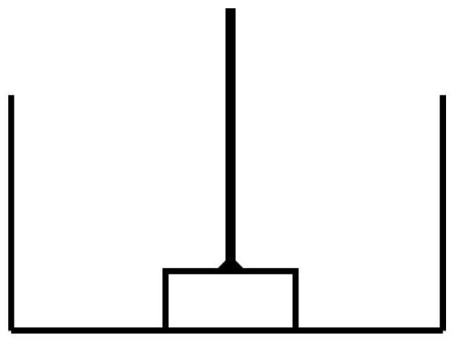
Third, in the current disordered sorting, the gripper at the end of the robot is designed as a long straight rod, and the gripping strategy is to pick up the end perpendicular to the surface of the workpiece, such as figure 1 As shown, the pose of the robot is directly related to the straight rod angle θ (the angle between the straight rod and the z′-axis direction of the material frame). Insufficient development, interference with the material frame, etc.
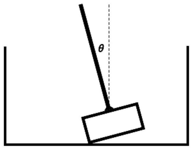
like figure 2 As shown, when the workpiece is tilted by 30°, the angle θ of the straight rod has reached 30°. If the tilt angle of the workpiece increases, the angle θ of the straight rod will also increase, which will cause problems such as insufficient arm extension of the robot and easy interference with the material frame.
This grasping strategy and hand grasping design can only grasp workpieces with an inclination angle within ±30°

Method used


Image

  • Workpiece grabbing method and device, computer equipment and storage medium
  • Workpiece grabbing method and device, computer equipment and storage medium
  • Workpiece grabbing method and device, computer equipment and storage medium

Examples


Embodiment 1

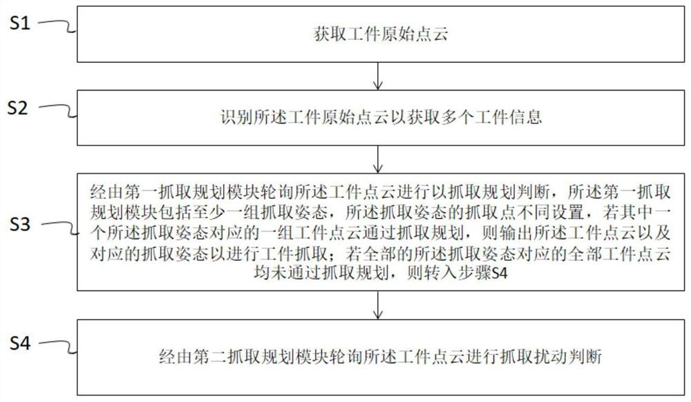
[0080] Such as image 3 As shown, the invention discloses a workpiece grasping method, which uses the terminal gripper to grasp the workpiece in the material frame. The terminal gripper includes a straight rod and a gripper assembly. The workpiece grasping method includes the following steps:

[0081] S1 acquires the original point cloud of the workpiece;

[0082] S2 identifies the original point cloud of the workpiece to obtain multiple workpiece information, and each workpiece information includes the workpiece point cloud and workpiece pose;

[0083] S3 polls the workpiece information via the first grasping planning module to determine the grasping planning. The first grasping planning module includes at least one group of grasping postures, and the grasping points of the grasping postures are set differently. If one of the grasping postures corresponds to A set of workpiece information passes the grasping plan, then output the workpiece information and the corresponding g...

Embodiment 2

[0123] Although the workpiece grasping method shown in Embodiment 1 solves the problems of product size and spatial position, the existing motion planning requires that the manipulator be extended into the material frame, and the grasping depends on the kinematics model of the manipulator body. If the straight rod angle When θ is greater than 30°, there are problems such as insufficient arm span of the robot and interference with the material frame. Especially in practical applications, the above problems are more obvious due to the limited space of the site.

[0124] On the basis of Embodiment 1, the present invention further provides a workpiece grasping method, which uses the end gripper to grasp the workpiece in the material frame, such as Figure 16 As shown, the end gripper 20 includes a straight rod 21 and a gripper assembly 22, the gripper assembly and the straight rod are set at an angle, and the straight rod is connected to the external robot arm so that the robot arm...

Embodiment 3

[0168] The present invention also discloses a workpiece grabbing device 10, which uses an end gripper to grip a workpiece, and the end gripper includes a straight rod and a gripper assembly connected with the straight rod;

[0169] Such as Figure 21 As shown, the workpiece grabbing device 10 includes:

[0170] The original point cloud acquisition module 11 is used to obtain the original point cloud of the workpiece;

[0171] The workpiece information acquisition module 12 is used to identify the original point cloud of the workpiece to obtain a plurality of workpiece information, and each workpiece information includes a workpiece point cloud and a workpiece pose;

[0172] The first grasping planning module 13 is used to poll the workpiece information to determine the grasping planning. The first grasping planning module includes at least one group of grasping posture judgment submodules, and the grasping posture in the grasping posture judgment submodule Different settings...


PUM


Abstract

The invention discloses a workpiece grabbing method. The method comprises the following steps that S1, an original point cloud of a workpiece is obtained; S2, the original point cloud of the workpiece is identified so as to obtain multiple pieces of workpiece information; and S3, a first grabbing planning module polls the workpiece information to conduct grabbing planning judgment, if all the workpiece information corresponding to all grabbing postures does not pass grabbing planning, operation turns into the step S4, and a second grabbing planning module polls the workpiece information to conduct grabbing disturbance judgment. By means of the method, the grabbing success rate can be effectively improved, and workpieces can be grabbed in a completely-disordered state.

Description

technical field [0001] The invention relates to a system and a control method for grabbing parts from a material frame, in particular to a workpiece grabbing method, device, computer equipment and storage medium. Background technique [0002] In the field of industrial manufacturing, the traditional loading and unloading system is realized based on automated tooling or manual methods. The workpiece is heavy, the manual operation is labor-intensive, and it is difficult to recruit corresponding workers. With the promotion of industrial-grade 3D cameras and the rise of 3D vision algorithms, the disorderly sorting and loading system based on 3D vision is expected to realize intelligence in the past manual or automated methods, and realize the industrial upgrading of automatic loading and unloading systems. [0003] The 3D visual guidance application grabs parts, grabs from the material frame stack, grabs from the accumulation chain, and grabs parts from the EHB conveyor system, ...

Claims


Application Information

Patent Timeline
Patent Type & Authority Applications(China)
IPC IPC(8): B25J9/16
CPCB25J9/1602
Inventor 高磊秦继昊
Owner SEIZET TECH SHEN ZHEN CO LTD
Learn More