
Concrete flow control system

A flow control, concrete technology, applied in the direction of unloading devices, etc., can solve the problems of waste, uncontrollable concrete speed and volume, etc.

Inactive Publication Date: 2021-05-28
江苏昆腾新材料科技有限公司
View PDF5 Cites 0 Cited by
  • Summary
  • Abstract
  • Description
  • Claims
  • Application Information

AI Technical Summary

Problems solved by technology

Concrete is generally used for mixing in concrete mixer trucks or mixers. In practical applications, due to the fixed outlet size of mixer trucks and mixers, the speed and volume of concrete poured out are also uncontrollable. In practical applications, more concrete is often poured out. cause waste

Method used


Image

  • Concrete flow control system
  • Concrete flow control system

Examples


Embodiment

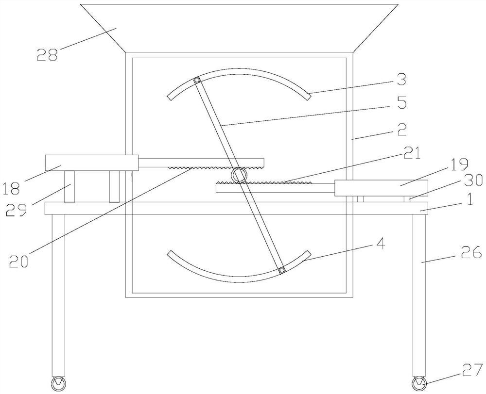
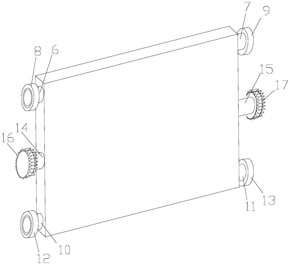
[0019] like figure 1 and figure 2 , this embodiment provides a concrete flow control system, including a support plate 1, a flow limiting box 2, an upper chute 3, a lower chute 4, a flow limiting plate 5, a first connecting column 6, a second connecting column 7, a first One bearing 8, the second bearing 9, the third connecting column 10, the fourth connecting column 11, the third bearing 12, the fourth bearing 13, the fifth connecting column 14, the sixth connecting column 15, the first connecting gear 16, the Two connecting gears 17, the first cylinder 18, the second cylinder 19, the first rack 20, the second rack 21, the third cylinder 22, the fourth cylinder 23, the third rack 24, the fourth rack 25, support Pin 26, universal wheel 27, feed hopper 28, high support frame 29, low support frame 30; Wherein the 3rd cylinder 22, the 4th cylinder 23, the 3rd rack 24, the 4th rack 25 and the first cylinder 18 , the second cylinder 19 , the first rack 20 , and the second rack 2...


PUM


Abstract

The invention discloses a concrete flow control system. The system comprises a support plate and a flow limiting box, wherein the flow limiting box penetrates the middle of the support plate, upper sliding grooves and lower sliding grooves are formed in the two sides of the flow limiting box correspondingly, a flow limiting plate is arranged in the flow limiting box, a first connecting column and a second connecting column are arranged on the two sides of one end of the flow limiting plate correspondingly, a first bearing is arranged at an outer ring of the first connecting column, a second bearing is arranged on an outer ring of the second connecting column, a third connecting column and a fourth connecting column are arranged at the two ends of the other side of the flow limiting plate correspondingly, a third bearing is arranged on an outer ring of the third connecting column, a fourth bearing is arranged on an outer ring of the fourth connecting column, a fifth connecting column and a sixth connecting column are arranged on the two sides of the middle of the flow limiting plate correspondingly, an outer ring of the fifth connecting column is connected to a first connecting gear, an outer ring of the sixth connecting column is connected to a second connecting gear, and the first bearing and the third bearing slide in the upper sliding grooves in front and back of the flow limiting box correspondingly.

Description

technical field [0001] The invention relates to the field of concrete construction, in particular to a concrete flow control system. Background technique [0002] Concrete refers to the artificial stone made of cement as the main cementitious material, mixed with water, sand, stones, chemical admixtures and mineral admixtures when necessary, mixed in appropriate proportions, uniformly stirred, compacted and cured. Concrete is generally used for mixing in concrete mixer trucks or mixers. In practical applications, due to the fixed outlet size of mixer trucks and mixers, the speed and volume of concrete poured out are also uncontrollable. In practical applications, more concrete is often poured out. cause waste. Contents of the invention [0003] Purpose of the invention: The technical problem to be solved by the present invention is to provide a concrete flow control system for the deficiencies of the prior art. [0004] In order to solve the above-mentioned technical pro...

Claims


Application Information

Patent Timeline
Patent Type & Authority Applications(China)
IPC IPC(8): B28C7/16
CPCB28C7/161
Inventor 胡承华滕宏军
Owner 江苏昆腾新材料科技有限公司
Learn More