Self-skinning device for plastic foam box

A technology of foamed plastics and self-skinning, which is applied in the field of foamed plastics and can solve the problems of insufficient foaming degree of materials, limited stirring range of stirring rods, and reduced production quality of foamed plastic boxes.

Inactive Publication Date: 2021-05-28
李岁敏
View PDF0 Cites 0 Cited by
  • Summary
  • Abstract
  • Description
  • Claims
  • Application Information

AI Technical Summary

Problems solved by technology

[0003] In order to solve the above technology, when the injection molding machine is used to foam and inject the plastic foam box, the material becomes fluid after heating, and the fluid moves back and forth in the foaming cavity by the thrust of the stirring rod, and the stirring range of the stirring rod is limited, and the accumulation in the foaming cavity The material on the right side of the cavity is subjected to a small stirring force, resulting in uneven mixing of the material and the foaming agent, resulting in insufficient foaming degree of some materials, resulting in a decrease in the production quality of the foamed plastic box. The invention provides a foamed plastic box that is automatically Crust equipment

Method used


Image

  • Self-skinning device for plastic foam box
  • Self-skinning device for plastic foam box
  • Self-skinning device for plastic foam box

Examples


Embodiment 1

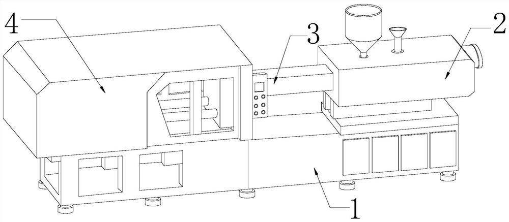
[0029] as attached figure 1 to attach Figure 6 Shown:

[0030] The invention provides a self-skinning equipment for a foamed plastic box, the structure of which includes a body 1, a mixer 2, a feeding pipe 3, and a mold 4. The mixer 2 is horizontally fixed on the top of the right end of the body 1, and the mold 4 is located On the left side of the device 2, the feed pipe 3 is installed between the mold 4 and the mixer 2.

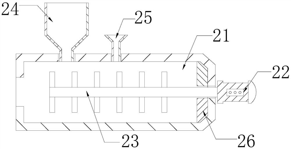
[0031] The mixer 2 is provided with a foaming chamber 21, a motor 22, a stirring rod 23, a hopper 24, a reagent tube 25, and a pushing mechanism 26. The foaming chamber 21 is located inside the mixer 2, and the motor 22 is horizontally fixed on In the middle part of the right end of the mixer 2, the stirring rod 23 is arranged in the middle part of the foaming cavity 21, and cooperates with the motor 22. The hopper 24 is vertically fixed on the top of the mixer 2, and the reagent tube 25 is located on the right side of the hopper 24. The pushing mechanis...

Embodiment 2

[0039] as attached Figure 7 to attach Figure 9 Shown:

[0040] Wherein, the clearing block s4 is provided with a card groove e1, a drainage groove e2, a clearing plate e3, and a reset bar e4, and the locking groove e1 is recessed on the top of the clearing block s4, and the drainage groove e2 runs through the middle and left sides of the clearing block s4. Between the sides, and communicate with the card slot e1, the clearing plate e3 is set on the top of the card slot e1, the reset strip e4 is installed between the bottom surface of the clearing plate e3 and the inner wall of the card slot e1, and the drainage groove e2 The bottom surface of the left end is inclined, which can reduce resistance and friction, and is conducive to the flow and discharge of material fluid along the drainage groove e2, reducing material retention inside the drainage groove e2, further reducing the gravity of the push plate a3, and speeding up the moving speed of the push plate a3 .

[0041] W...


PUM


Abstract

The invention discloses a self-skinning device for a plastic foam box. The self-skinning device structurally comprises a machine body, a mixer, a conveying pipe and a die. The mixer is horizontally fixed to the top of the right end of the machine body; the die is located on the left side of the mixer; and the conveying pipe is installed between the die and the mixer. Because the stirring force applied to a material stacked on the right side in a foaming cavity is small, the material is not uniformly mixed with a foaming agent. The material in the right side of the foaming cavity is pushed forwards by a push plate of a pushing mechanism, the foaming degree of the material is increased because of uniform mixing of the material and the foaming agent, and the production quality of the plastic foam box can be improved. Because the material forming consolidation time is short, the material staying on the inner wall of the foaming cavity and the outer wall of the right end of the stirring rod is prone to solidification, a clearing plate clears away the material on the inner wall of the foaming cavity and the outer wall of the right end of the stirring rod when a clearing block moves along with the push plate, less material stays on the inner wall of the foaming cavity and the outer wall of the right end of the stirring rod, and forward conveying and injection moulding of the material are facilitated.

Description

technical field [0001] The invention belongs to the field of foamed plastics, and more specifically relates to a self-skinning device for foamed plastics boxes. Background technique [0002] Using injection molding machine to process and produce foam plastic box, feed polystyrene material into the mixer through the hopper, and feed foaming agent through the reagent tube, the motor drives the stirring rod to rotate, so that the material in the foaming cavity and the reagent are mixed and then discharged The feeding pipe is injected into the mold to make the foamed plastic box foamed; in the prior art, when the plastic foamed box is foamed and injected by an injection molding machine, the material becomes fluid after heating, and the fluid is pushed by the stirring rod in the foaming cavity It moves back and forth, and the stirring range of the stirring rod is limited, and the material accumulated on the right side of the foaming cavity is subjected to a small stirring force, ...

Claims


Application Information

Patent Timeline
Patent Type & Authority Applications(China)
IPC IPC(8): B29C44/34B08B9/087
CPCB08B9/087B29C44/3442B29C44/35
Inventor 刘雪凤
Owner 李岁敏
Why Eureka
Try Eureka