Gas-assisted mold gas needle and gas-assisted equipment

A gas-needling and gas-assisted technology, applied in the field of gas-assisted injection molding equipment, to achieve the effect of increasing the production quantity, increasing the air intake and air return, and shortening the production cycle

Pending Publication Date: 2021-05-28
NINGBO FUERDA SMARTECH CO LTD
View PDF6 Cites 0 Cited by
  • Summary
  • Abstract
  • Description
  • Claims
  • Application Information

AI Technical Summary

Problems solved by technology

[0009] The traditional air needle structure is a fixed air needle. During the gas-assisted injection molding process, the gas can only enter and return air through the matching gap between the air needles.

Method used


Image

  • Gas-assisted mold gas needle and gas-assisted equipment
  • Gas-assisted mold gas needle and gas-assisted equipment
  • Gas-assisted mold gas needle and gas-assisted equipment

Examples


Embodiment Construction

[0029] The present invention will be further described below in conjunction with the accompanying drawings and specific embodiments.

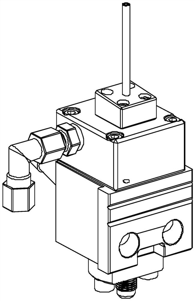
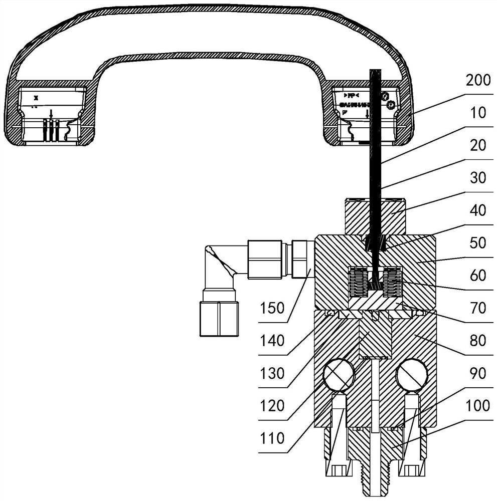
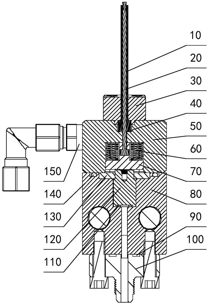
[0030] Examples, see attached Figure 1-7 , a gas-assisted mold air needle, comprising an outer air needle 10, an inner air needle 20, an outer needle positioning block 30, an outer needle sealing ring 40, an air needle holder 50, a compression spring 60, an inner needle movable block 70, a hydraulic cylinder Fixed seat 80, hydraulic joint sealing ring 90, hydraulic joint 100, hydraulic cylinder sealing ring 110, hydraulic cylinder 120, hydraulic cylinder positioning block 130, fixed seat sealing ring 140, air joint 150;

[0031] The air needle holder 50 has an upper groove and a lower groove, and there is a circular hole for the inner air needle 20 to pass between the upper groove and the lower groove; the upper end surface of the hydraulic cylinder holder 80 has a hydraulic groove, and the hydraulic groove The bottom surface also has a mediu...


PUM


Abstract

The invention relates to a gas-assisted mold gas needle. The gas-assisted mold comprises a gas connector, a fixing base, an outer gas needle, an inner gas needle and a driving mechanism, wherein the outer gas needle is fixedly installed on the fixing base and provided with a penetrating through hole, the two ends of the through hole are the gas inlet end and the gas outlet end correspondingly, the inner gas needle comprises a rear end, a rod body and a front end, the rear end is located inside the fixing base, the front end and the rod body penetrate into an outer gas needle through hole, the driving mechanism is fixedly connected to the rear end of the inner gas needle and can drive the inner gas needle to reset or move, after the inner gas needle is reset, the front end of the inner gas needle tightly matches with the gas outlet end of the outer gas needle to seal the gas outlet end of the outer gas needle, after the inner gas needle moves, a gap is formed between the front end of the inner gas needle and the gas outlet end of the outer gas needle to open the gas outlet end of the outer gas needle. According to the gas-assisted mold gas needle and gas-assisted equipment, a gas needle structure is improved, the inner gas needle can move up and down so as to open or close the gas inlet of the outer gas needle, a user does not need to worry about backflow of plastic melt in the injection molding stage during closing, the gas inlet gap of the gas needle can be increased when inflation is opened, the gas inlet and return amount in unit time is greatly increased, and the gas inlet and return time is shortened.

Description

technical field [0001] The invention relates to the field of gas-assisted injection molding equipment, in particular to a gas-assisted mold gas needle and gas-assisted equipment. Background technique [0002] Gas-assisted molding refers to injecting inert high-pressure nitrogen gas when the plastic is filled into the cavity (75%~99.9%), and the gas pushes the molten plastic to continue filling the cavity, and replaces the plastic holding process with gas pressure. Injection molding technology. Gas-assisted molding has many advantages, such as reducing the residual stress of the product so that the product does not deform; solving and eliminating the problem of sink marks on the product surface, which is applied to products with large thickness changes; shortening the production molding cycle time of products and improving production efficiency; saving plastic raw materials . [0003] The process of gas-assisted injection molding can be summarized as: [0004] Injection mo...

Claims


Application Information

Patent Timeline
Patent Type & Authority Applications(China)
IPC IPC(8): B29C45/34B29C45/57B29C45/17
CPCB29C45/34B29C45/57B29C45/1703
Inventor 郑文闯陈科卓健高吉森徐益明
Owner NINGBO FUERDA SMARTECH CO LTD
Why Eureka
Try Eureka