
Installing structure of forced side feeding machine of double-screw extruder

A twin-screw extruder and installation structure technology, which is applied in the field of twin-screw extruders, can solve problems such as difficulty in assembly and maintenance of gearboxes, difficulty in installation and positioning adjustment of side feeding barrels, and spraying of materials at the inlet of side feeding barrels. , to achieve the effect of saving assembly and maintenance time, convenient installation and operation, and simple assembly structure

Pending Publication Date: 2021-05-28
NANJING GIANT MACHINERY
View PDF0 Cites 0 Cited by
  • Summary
  • Abstract
  • Description
  • Claims
  • Application Information

AI Technical Summary

Problems solved by technology

[0007] Purpose of the invention: The purpose of the invention is to provide an improved installation structure of the forced side feeder of the twin-screw extruder, which solves the difficulty in the installation and positioning adjustment of the side feeder of the forced side feeder, and the side feeder cannot be cooled by water. The phenomenon of material spraying at the feed inlet and the difficulty in assembly and maintenance of the gearbox

Method used


Image

  • Installing structure of forced side feeding machine of double-screw extruder
  • Installing structure of forced side feeding machine of double-screw extruder
  • Installing structure of forced side feeding machine of double-screw extruder

Examples


Embodiment Construction

[0035] The present invention will be further explained below in conjunction with the accompanying drawings.

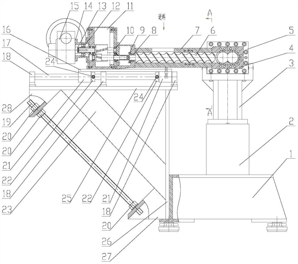
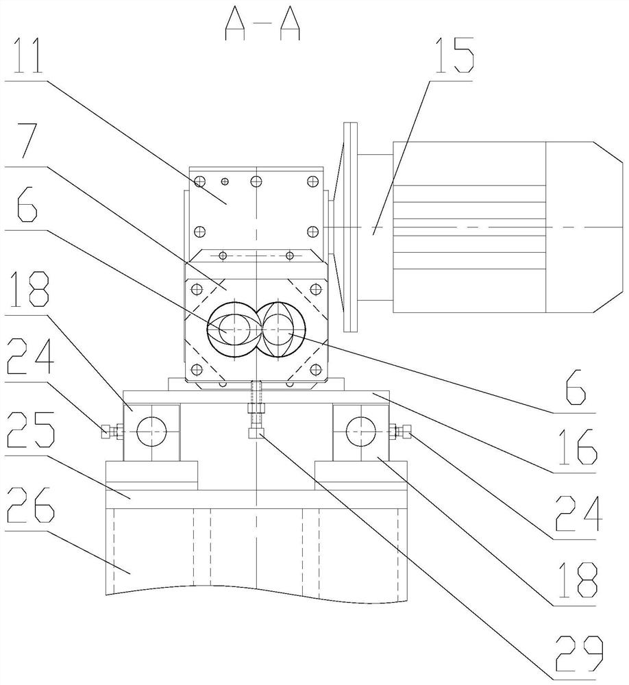
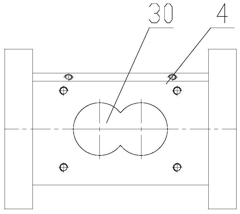
[0036] Such as figure 1 , 2 Shown in and 3, a kind of twin-screw extruder forced side feeder installation structure of the present invention comprises a forced side feeder, and the forced side feeder consists of a side feeding cylinder 7, a pair of intermeshed side feeders The screw rod 6, the connecting body 10, the gear box 11, the connecting flange 14 and the reduction motor 15 are combined. The side feed barrel 7 of the forced side feeder is connected to the side feed port 30 of the side feed barrel 4 of the twin-screw extruder.

[0037] Such as image 3 and 4 As shown, the side feeding cylinder flange II5 of the side feeding cylinder 4 is installed above the cylinder support 3, the lower part of the cylinder support 3 is installed on the upper part of the support base 2, and the lower part of the support base 2 is connected to the twin-screw The upper part of...


PUM


Abstract

The invention discloses an installing structure of a forced side feeding machine of a double-screw extruder. The installing structure comprises the forced side feeding machine, a forced side feeding machine side feeding cylinder is connected to a double-screw extruder side feeding cylinder body, the front portion of the side feeding cylinder is provided with a water inlet connector, a cooling water channel and a water drainage connector, a connecting flange at the rear end of the side feeding cylinder is connected to the front end face of a gearbox through a connecting body, the rear end face of the gearbox is connected to the front end face of a gear motor through the connecting flange, the bottom of the gearbox is installed on the upper portion of a feeding machine bottom plate, a sliding bearing is installed on the lower portion of the feeding machine bottom plate and installed on a sliding bearing sliding rod, and a limiting ring is installed on the sliding bearing sliding rod and fixed to the sliding bearing sliding rod through a fixing screw to limit a sliding bearing. According to the installing structure of the forced side feeding machine of the double-screw extruder, the problems that the forced side feeding machine side feeding cylinder is difficult to install, position and adjust, and the side feeding cylinder cannot be cooled through water, so that a feeding port sprays materials, and the gearbox is difficult to assemble and maintain are solved.

Description

technical field [0001] The invention relates to a twin-screw extruder, in particular to an installation structure for a forced side feeder of a twin-screw extruder. Background technique [0002] In the process of mixing and modifying polymer materials, the twin-screw extruder uses a forced side feeder to feed specific materials into the side feeding barrel of the twin-screw extruder according to the process requirements, and polymerizes The performance of the material can be improved by adding specific materials. After the polymer is blended and modified by adding specific materials, a polymer material that meets special needs and has higher performance can be obtained. [0003] The currently used twin-screw extruder forced side feeder installation structure has the following disadvantages: [0004] 1. The forced side feeder is installed on the cart, when connecting the forced side feeder to the side feeding barrel of the twin-screw extruder, it is necessary to adjust the s...

Claims


Application Information

Patent Timeline
IPC IPC(8): B29C48/82B29C48/25B29C48/40
CPCB29C48/252B29C48/40B29C48/82
Inventor 霍庆宪迟华健罗磊霍春雨
Owner NANJING GIANT MACHINERY
Learn More