AI technical title is built by PatSnap AI team. It summarizes the technical point description of the patent document.
A cutting device and steel technology, applied in the engineering field, can solve problems such as single function and slow speed
Active Publication Date: 2021-05-28
嘉善立业金属制品股份有限公司
View PDF5 Cites 2 Cited by
Summary
Abstract
Description
Claims
Application Information
AI Technical Summary
This helps you quickly interpret patents by identifying the three key elements:
Problems solved by technology
Method used
Benefits of technology
Problems solved by technology
[0002] The steel cutting and binding device is a common construction machine, but the general steel cutting and binding device is manually operated, the speed is slow, and the function is relatively single
Method used
Image
Click on the blue label to locate the original text in one second.
Reading with bidirectional positioning of images and text.
Examples
specific Embodiment approach 1
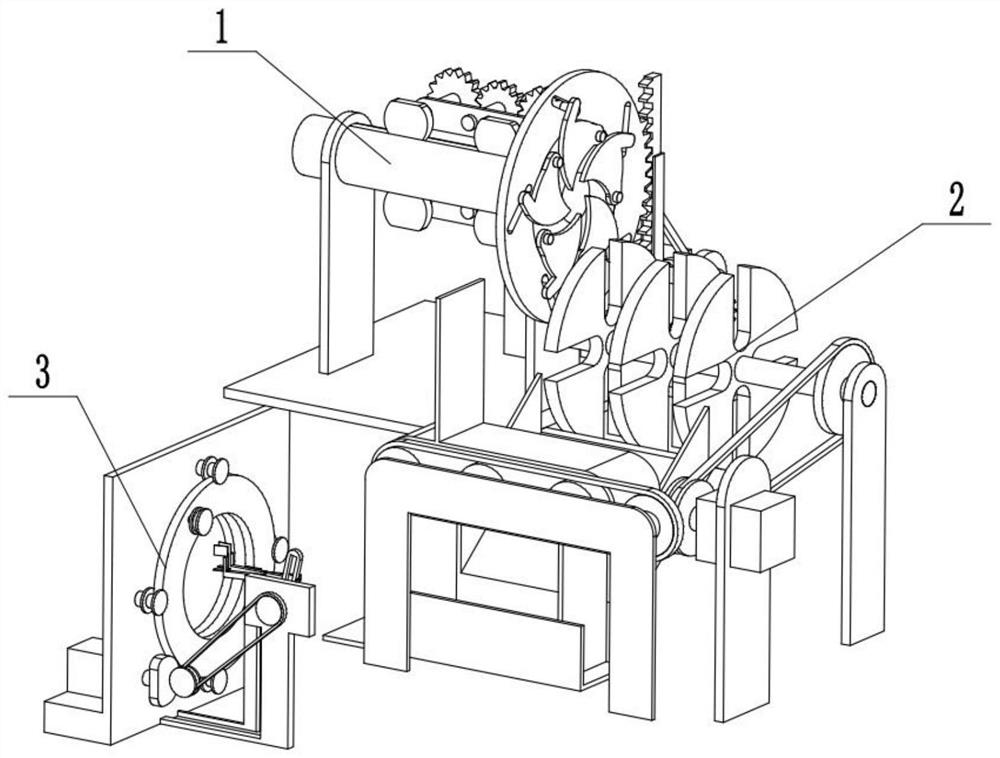
[0026]Bonded belowFigure 1-10In the present embodiment, an automatic steel cutting bundling device includes a cutting device 1, a transmission device 2, a bundled apparatus 3, and the cutting device 1 is connected to the transmission device 2, and the cutting device 1 is connected to the bundled apparatus 3.
specific Embodiment approach 2
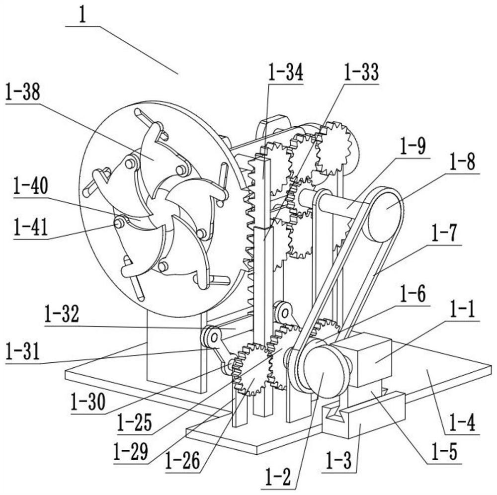
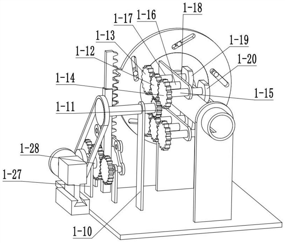
[0028]Bonded belowFigure 1-10In this embodiment, the present embodiment will further explain the embodiment, and the cutting device 1 includes a motor 1-1, a rotary one 1-2, a motor base 1-3, a base boss 1-4, a slider 1-5, Runner 2 1-6, belt 1-7, runner three 1-8, connecting rod 1-9, stent one 1-10, gear 1-11, gear 2 1-12, gear Three 1-13, gear four 1-14, connecting rod two 1-15, connecting rod three 1-16, connecting rod 4 1-17, bracket 2 1-18, half wheel 1-19, half turn wheel 2 1-20, transmission tube 1-21, slot 1-22, bracket three 1-23, bracket 4 1-25, gear six 1-26, bracket 5 1-27, connecting rod 5 1 -28, bracket six 1-29, connecting rod 6 1-30, function rod 1-31, long rod 1-33, straight tooth 1-34, functional disk 1-35, small slot 1 -36, small cylindrical 1-37, cutting blade 1-38, nozzle 1-39, inner disc 1-40, hinge column 1-41, motor one 1-1 and wheel 1-2 fixed connection, The motor 1-1 is fixed to the slider 1-5, the motor base 1-3 is slidable with the slider 1-5, and the moto...
specific Embodiment approach 3
[0031]Bonded belowFigure 1-10In the present embodiment, the present embodiment will further explain the embodiment, and the transmission device 2 includes a motor 2-1, a struts 2-2, a rotary four 2-3, a belt 2-4, a strut 2 2 -5, runner five 2-6, function long rod 2-7, turntable 2-8, card slot 2-9, slide 2-10, transmission inner column 2-11, transmission 3-12, transmission belt 2 -13, Function Board 2-14, belt three 2-15, collect box 2-16, pillar three 2-17, runner six 2-18, fixed column 2-19, motor 2-1 and pillar one 2- 2 fixed connection, motor 2-1 and rotary four 2-3 fixed connections, rotary four 2-3 with belt 2-4, belt 2-4 with the runner five 2-6, transfer Wheel 5 2-6 is fixedly connected to function long rod 2-7, and the function long rod 2-7 is rotated to the pillar 2-5, and the four turntables 2-8 are fixedly connected to the functional long rod 2-7, four cards Both the slots 2-9 are provided on the turntable 2-8, the transmission inner column 2-11 is rotated to the transmis...
PUM
Abstract
The invention relates to the field of engineering, in particular to an automatic steel cutting and binding device. The steel cutting length and cutting speed can be changed by changing the rotating speed of a gear; steel pipes can be conveyed in batches; and intermittent cutting is achieved, a tape can be pulled out to bind steel, when a sliding block slides in a motor base, the rotating speed of a second rotating wheel is changed, then the transmission speed of a first belt is changed, rotation of a third rotating wheel is changed, the rotating speed of a first connecting rod is changed, the rotating speed of a first gear is changed, then the rotating speed of a second gear and the rotating speed of a third gear are changed, rotation of a first semi-rotating wheel and a second semi-rotating wheel is changed, the length of forward conveying of the steel is changed, and when the sliding block slides in the motor base, the rotating speed of a fifth gear, the rotating speed of two sixth gears and the speed of vertical reciprocating motion of straight teeth can be changed, and then the opening and closing speed of a cutting blade is changed, so that the length of a cut steel pipe is further changed.
Description
Technical field[0001]The present invention relates to an engineering field, and more specifically is an automatic steel cutting bundle device.Background technique[0002]Steel cutting bundles are common construction machinery, but general steel cutting bundles manually operate, slower speed, and a single function.Inventive content[0003]It is an object of the present invention to provide an automatic steel cutting bundling device that can change the length and cutting speed of the cutting steel by changing the rotational speed of the gear; the steel pipe can be transferred; can be brought to a binding steel.[0004]The object of the present invention is achieved by the following technical solutions:[0005]An automatic steel cutting bundle device including a cutting device, a transmission device, a bundling device, and the cutting device is connected to a transmission device, and the cutting device is connected to the bundling device.[0006]As a further optimization of the present technical...
Claims
Application Information
Patent Timeline
Application Date:The date an application was filed.
Publication Date:The date a patent or application was officially published.
First Publication Date:The earliest publication date of a patent with the same application number.
Issue Date:Publication date of the patent grant document.
PCT Entry Date:The Entry date of PCT National Phase.
Estimated Expiry Date:The statutory expiry date of a patent right according to the Patent Law, and it is the longest term of protection that the patent right can achieve without the termination of the patent right due to other reasons(Term extension factor has been taken into account ).
Invalid Date:Actual expiry date is based on effective date or publication date of legal transaction data of invalid patent.

