A cloth cutting device for textile fabric processing with replaceable blades
What is Al technical title?
Al technical title is built by PatSnap Al team. It summarizes the technical point description of the patent document.
A technology for textile fabrics and blades, applied in the field of fabrics, can solve the problems of cumbersome disassembly, movement of fabrics, inconvenient blade replacement, etc., and achieves the effects of high feeding accuracy, easy replacement, and easy disassembly and assembly.
Active Publication Date: 2022-04-05
苏州帛乐纺织有限公司
View PDF5 Cites 0 Cited by
Summary
Abstract
Description
Claims
Application Information
AI Technical Summary
This helps you quickly interpret patents by identifying the three key elements:
Problems solved by technology
Method used
Benefits of technology
Problems solved by technology
[0004] The purpose of the present invention is to solve the problems in the prior art that the cloth cutting machine in the prior art needs to be cumbersomely disassembled when replacing the cutting blade, so that it is not convenient to replace the blade, and when cutting, the fabric will move, which will cause The cutting part of the fabric is not neat enough, so the cutting effect is not good, and there is no automatic feeding function. It is necessary to manually place the fabric under the blade, so that the cutting length needs to be controlled manually, which is not easy to use. Cloth cutting device for textile fabric processing with blade replacement
Method used
Image
Click on the blue label to locate the original text in one second.
Reading with bidirectional positioning of images and text.
Examples
Embodiment Construction
[0025] The following will clearly and completely describe the technical solutions in the embodiments of the present invention with reference to the accompanying drawings in the embodiments of the present invention. Obviously, the described embodiments are only some of the embodiments of the present invention, not all of them.
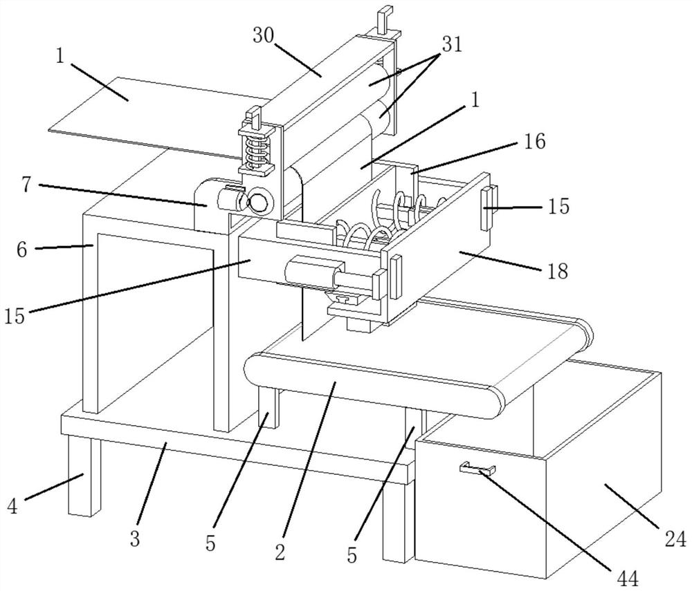
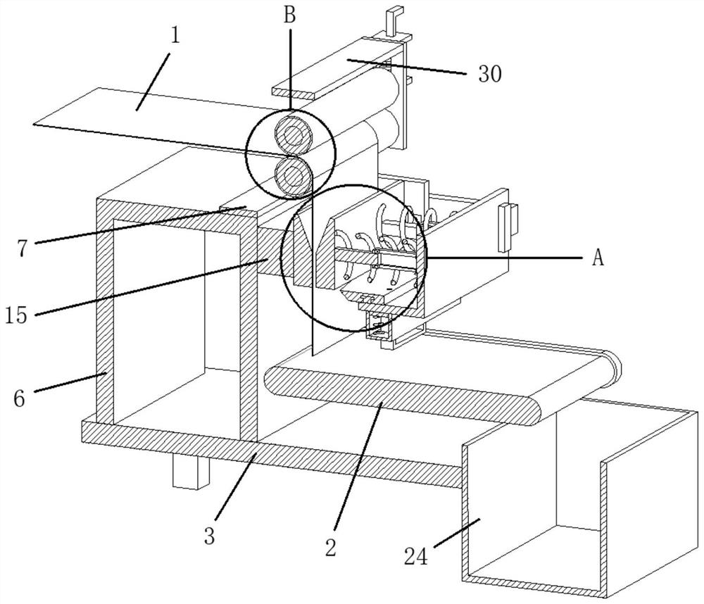
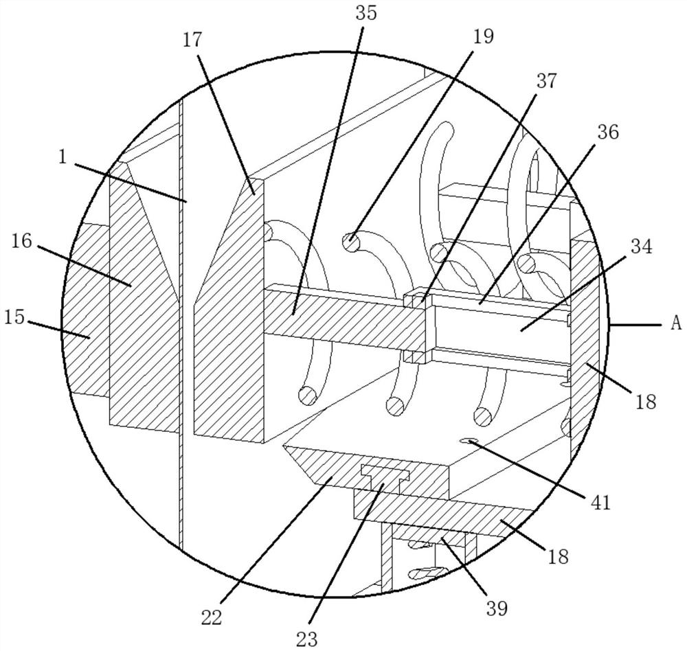
[0026] refer to Figure 1-8, a cloth cutting device for textile fabric processing that can replace blades, comprising a fabric 1, a conveyor belt 2, a worktable 3 is provided on one side of the fabric 1, a plurality of support legs 4 are fixedly provided on one side of the workbench 3, and the conveyor belt 2 One side is fixed with a number of support rods 5, the other ends of the support rods 5 are fixedly connected to one side of the worktable 3, one side of the worktable 3 is fixed with an inverted U-shaped frame 6, and one side of the inverted U-shaped frame 6 A Z-shaped hollow frame 7 is fixedly arranged, and one side of the Z-shaped hollow frame 7...
PUM
Abstract
The invention relates to the technical field of fabrics, in particular to a cloth cutting device for textile fabric processing that can replace blades, including fabrics and conveyor belts, a worktable is provided on one side of the fabric, and a number of support legs are fixed on one side of the worktable , one side of the conveyor belt is fixed with a number of support rods, the other end of the support rods is fixedly connected to one side of the worktable, one side of the worktable is fixed with an inverted U-shaped frame, and one side of the inverted U-shaped frame is fixed with a Z-shaped Hollow frame, one side of the Z-shaped hollow frame is provided with a drive shaft. In the present invention, a driving shaft, a servo motor, an active lowering barrel, a pressing shaft, an active hole, a driven pressing barrel, a U-shaped material clamping seat, a sliding clamping seat, an L-shaped sliding frame, a spring, and a telescopic hydraulic cylinder are arranged. , bevel edge cutting knife, T-shaped fixed strip, so that it has the functions of automatic feeding, precise feeding, automatic cutting, anti-deviation, easy tool change, automatic collection and so on.
Description
technical field [0001] The invention relates to the technical field of fabrics, in particular to a cloth cutting device for textile fabric processing that can replace blades. Background technique [0002] Fabric is the material used to make clothing. As one of the three elements of clothing, fabric can not only interpret the style and characteristics of clothing, but also directly affect the color and shape of clothing. Strips of fabric are cut into lengths of fabric. [0003] Cloth cutting machines in the prior art need to be cumbersomely disassembled when replacing the cutting blades, so that it is not convenient to replace the blades, and when cutting, the fabric will move, which will cause the cutting of the fabric to be not neat enough, so that the cutting effect is not good. It is good, and there is no automatic feeding function. It is necessary to manually place the cloth under the blade, so that the cutting length needs to be controlled manually, which is not easy t...
Claims
Application Information
Patent Timeline
Application Date:The date an application was filed.
Publication Date:The date a patent or application was officially published.
First Publication Date:The earliest publication date of a patent with the same application number.
Issue Date:Publication date of the patent grant document.
PCT Entry Date:The Entry date of PCT National Phase.
Estimated Expiry Date:The statutory expiry date of a patent right according to the Patent Law, and it is the longest term of protection that the patent right can achieve without the termination of the patent right due to other reasons(Term extension factor has been taken into account ).
Invalid Date:Actual expiry date is based on effective date or publication date of legal transaction data of invalid patent.