A kind of method and device for pulling out the roller below the steel rail for dragging the steel rail

A technology of pulling devices and rollers, which is applied in the direction of track, track laying, track maintenance, etc., can solve the problems of increased labor costs, slow speed, low efficiency, etc., achieve the effect of standard placement and posture, and improved operating efficiency

Active Publication Date: 2022-07-01
ZHUZHOU XUYANG ELECTRICAL & MECHANICAL TECH DEV CO LTD +3
View PDF0 Cites 0 Cited by
  • Summary
  • Abstract
  • Description
  • Claims
  • Application Information

AI Technical Summary

Problems solved by technology

[0004] It can be seen from the manual pushing of the rollers from under the rails that the operation of manually pushing out the rollers not only increases the labor cost, but also is slow and inefficient. At the same time, it is difficult to make the position of the rollers manually pushed and placed neatly. Fast and accurate grasping by one-step manipulators is very unfavorable, all of which will seriously affect the progress of the entire track laying system

Method used


Image

  • A kind of method and device for pulling out the roller below the steel rail for dragging the steel rail
  • A kind of method and device for pulling out the roller below the steel rail for dragging the steel rail
  • A kind of method and device for pulling out the roller below the steel rail for dragging the steel rail

Examples


Embodiment 1

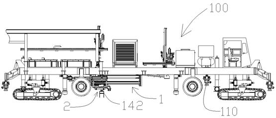
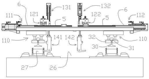
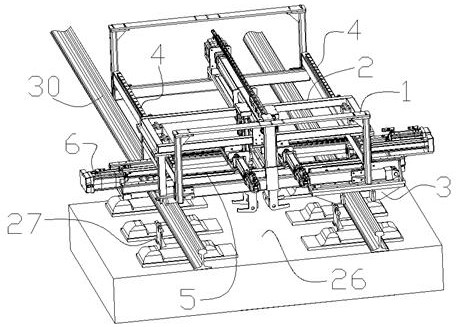
[0042] like figure 1 , 2 As shown in Fig. 3, a device designed according to the above-mentioned method for pulling out the roller 27 used for the towing of the steel rail 30 under the steel rail 30 includes the rail lifting and sliding mechanism 110 arranged on both sides of the roller recovery vehicle 100, The active frame 2 on the car 100, the retrograde parking mechanism disposed between the active frame 2 and the recovery car 100, the lateral drive mechanism disposed on the active frame 2, the longitudinal fine-tuning mechanism on the lateral drive mechanism, and the longitudinal fine-tuning mechanism The lifting mechanism on the upper part and the hook part arranged at the lower end of the lifting mechanism. The rail lifting and sliding mechanism 110 arranged on both sides of the roller recovery vehicle 100 has two horizontally arranged pulleys 32, which are respectively added between the rail head 31 and the rail bottom on both sides of the rail 30, for pressing the rai...

Embodiment 2

[0064] like Figure 10 As shown, a device for pulling out the roller 27 used for dragging the steel rail under the steel rail 30 is different from the first embodiment in that the hook component includes a hook frame 33 and an electromagnetic solenoid disposed at the lower end of the hook frame 33. The suction cup 34, the electromagnetic suction cup 34 faces the left or right side of the track bed 26 under the vehicle belly. Correspondingly, the front and rear ends of the roller frame 28 are made of magnetic materials such as iron, or magnetic plates are directly installed. A strong electromagnetic coil is arranged in the electromagnetic chuck 34, and the suction and release of the drum frame are controlled by turning off the current. In application, the electromagnetic coil is energized, so that the electromagnetic chuck 34 is close to the drum frame 28, and after sucking the drum frame 28, the drum 27 is dragged to a limited position, and then the power is turned off and re...


PUM


Abstract

The invention discloses a method and a device for pulling out a roller used for towing the steel rail under the steel rail. The rail is lifted, and the lift-sliding mechanism slides forward with the vehicle on the bottom surface of the rail head on both sides of the rail, so that the rail section lifted off the drum moves forward continuously. A two-way tractor that can pull the roller out from the bottom of the rail. During operation, the tractor is reversed on the roller recovery vehicle when the roller recovery vehicle moves forward, so that the tractor and the track bed remain relatively stationary and maintained for a period of time. After a period of time, the pulling device completes the action of pulling the drum out from the underside of the raised rail, and then moves forward at a higher speed than the forwarding speed of the drum recovery vehicle to start the next operation. The advantage is that the roller pressed under the rail can be quickly pulled out and placed in the set position accurately and standardized.

Description

technical field [0001] The invention relates to a method and a device for pulling out a roller used for dragging the steel rail under the steel rail, and belongs to the technical field of railroad track laying for rail transit. Background technique [0002] In the automatic track laying system, a roller is used which temporarily carries the rail and enables the rail to be dragged on it. In the automatic track laying process, the front car pre-places rollers on both sides of the track bed according to the gauge to provide temporary support with minimal frictional resistance for the rails on both sides of the back that fall and move forward. The length of about 500 meters) falls on the roller and stops moving. At this time, there is no roller placed under the rail with a length of about ten meters at the rear end. Connect the rear end of the rail on both sides to the front end of the rail that has been laid before. After that, it is necessary to extract all the rollers that a...

Claims


Application Information

Patent Timeline
Patent Type & Authority Patents(China)
IPC IPC(8): E01B29/16
CPCE01B29/16
Inventor 邓建华喻国梁段启楠莫子坤卫海津华正兴田庆
Owner ZHUZHOU XUYANG ELECTRICAL & MECHANICAL TECH DEV CO LTD
Why Eureka
Try Eureka