Building construction device and construction method

A technology of building construction and equipment, which is applied in the direction of construction, building structure, and building material processing, etc. It can solve the problems of not being able to fix brick walls with nails, and achieve the effect of preventing solidification and drying and strengthening the wall

Active Publication Date: 2021-05-28
湖南天禹建设有限公司
View PDF7 Cites 2 Cited by
  • Summary
  • Abstract
  • Description
  • Claims
  • Application Information

AI Technical Summary

Problems solved by technology

The shortcoming of this invention is that the brick wall of building laying cannot be nailed and fixed

Method used


Image

  • Building construction device and construction method
  • Building construction device and construction method
  • Building construction device and construction method

Examples


specific Embodiment approach 1

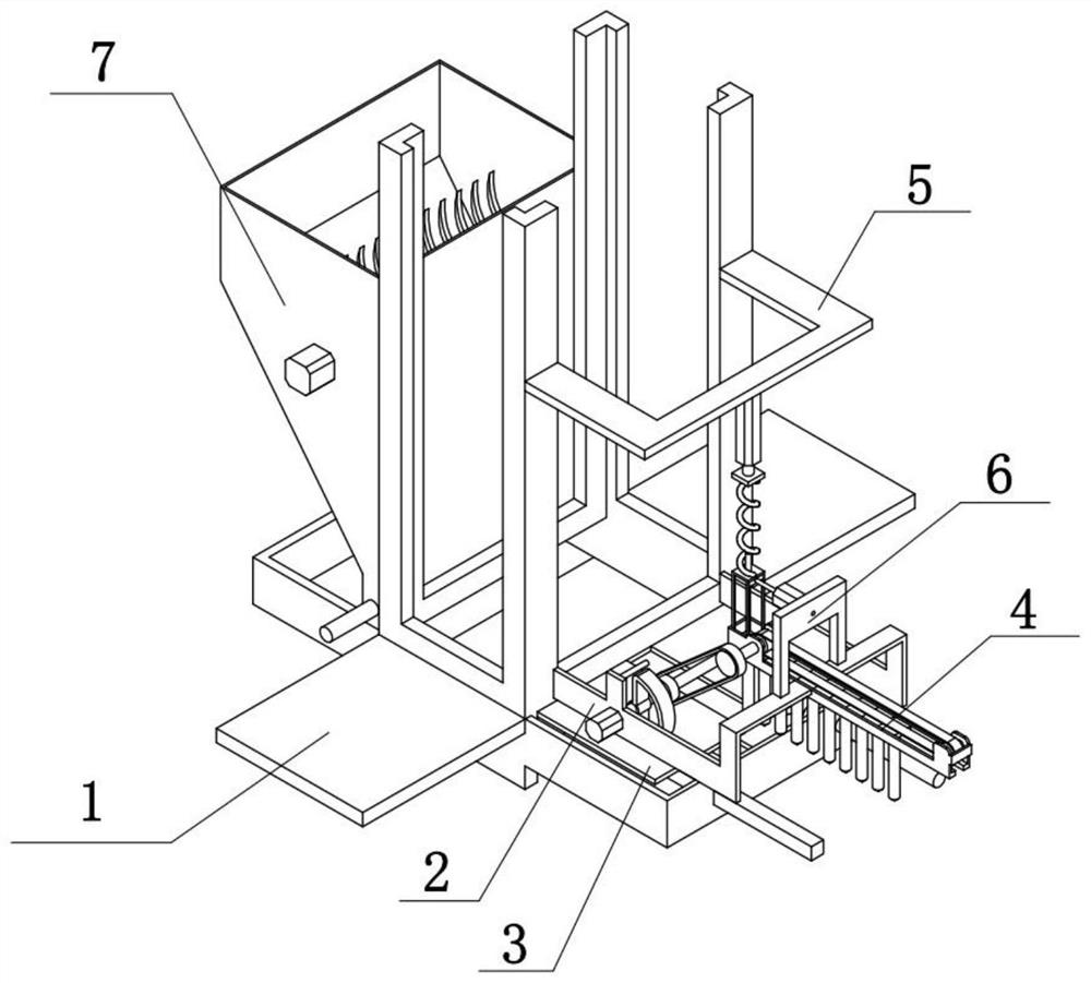
[0035] Combine below Figure 1-8 Describe this embodiment, a building construction equipment, including a walking assembly 1, a driving assembly 2, a pushing assembly 3, a nail feeding assembly 4, a power storage assembly 5, a material retaining assembly 6 and a paint assembly 7, the driving assembly 2 is fixedly connected On the walking assembly 1, the pushing assembly 3 is slidably connected to the walking assembly 1, the driving assembly 2 and the pushing assembly 3 are engaged and driven, the nail feeding assembly 4 is fixedly connected to the driving assembly 2, and the driving assembly 2 and the nail feeding assembly 4 are driven by a belt , the power storage assembly 5 is fixedly connected to the walking assembly 1, the stopper assembly 6 is fixedly connected to the driving assembly 2, the stopper assembly 6 and the power storage assembly 5 are slidingly connected, and the paint assembly 7 is fixedly connected to the walking assembly 1.

[0036] The automatic intermitte...

specific Embodiment approach 2

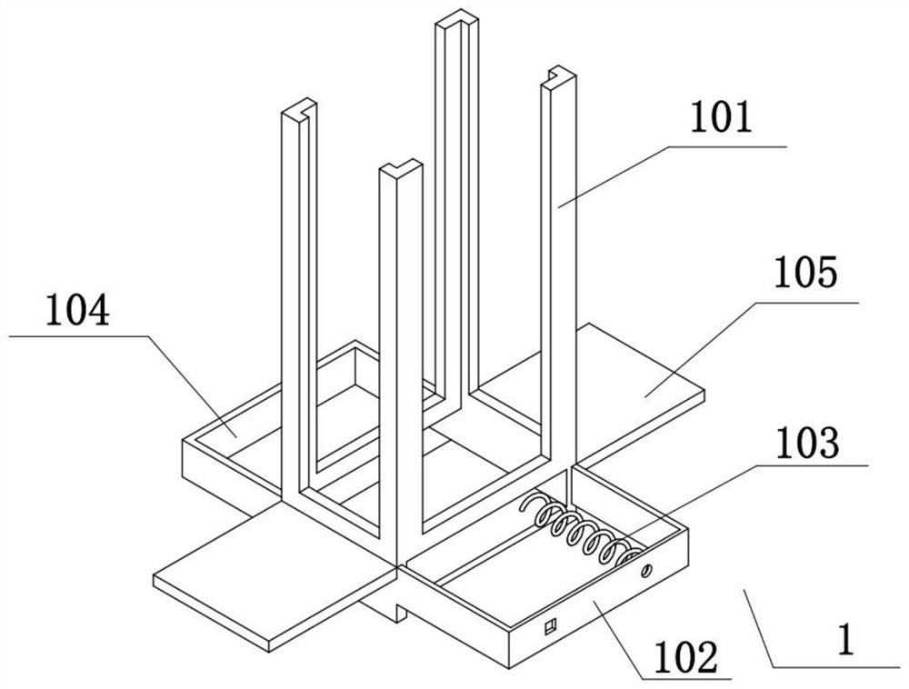
[0038] Combine below Figure 1-8Describe this embodiment, described walking assembly 1 comprises falling brick support 101, auxiliary frame 102, extension spring 103, limit frame 104 and walking support 105, the right end of falling brick support 101 is fixedly connected with auxiliary frame 102, and on auxiliary frame 102 Fixedly connected with extension spring 103, the left end of falling brick support 101 is fixedly connected with limit frame 104, and the front and rear ends of falling brick support 101 are all fixedly connected with walking support 105, and all are fixedly connected with walking mechanism on two walking supports 105.

specific Embodiment approach 3

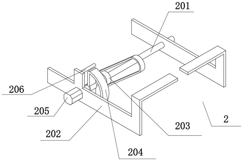
[0040] Combine below Figure 1-8 To illustrate this embodiment, the drive assembly 2 includes a drive shaft 201, a drive frame 202, a transport wheel 203, a drive wheel 204, a drive motor 205, and a pressure sensor I 206. The drive shaft 201 is rotatably connected to two drive frames 202, two The driving frames 202 are all fixedly connected on the brick falling support 101, the driving shaft 201 is fixedly connected with the transport wheel 203 and the driving wheel 204, the driving motor 205 is fixedly connected on one of the driving frames 202, and the driving shaft 201 is fixedly connected on the driving motor 205 On the output shaft, the pressure sensor I 206 is fixedly connected to one of the drive frames 202 .


PUM


Abstract

The invention relates to the technical field of equipment, and particularly relates to a building construction device and a construction method. The building construction device and the construction method have the advantage that a brick wall laid on a building can be nailed and fixed. The construction method of the building construction device comprises the following steps that S1, bricks are placed in a walking assembly, and concrete is added into a coating assembly; S2, the walking assembly is started to move at a fixed length, a driving assembly is started to periodically mesh with and drive a pushing assembly to push the bricks to be laid, and pushed rotating blocks are coated with the concrete; S3, after a force storage assembly stores force, nails provided by an impact nail supply assembly are released to fixedly connect the laid rotating blocks; and S4, the walking assembly is started again to walk, and the next brick is laid.

Description

technical field [0001] The present invention relates to the technical field of equipment, more specifically to a building construction equipment and a construction method. Background technique [0002] The invention with the publication number CN111612485A discloses an intelligent building construction equipment, a quality monitoring method and system based on the Internet of Things, wherein the intelligent building construction equipment is provided with a sliding seat driven by a drive motor on the slide rail, and a A first touch switch is provided, a second touch switch is provided on the sliding seat, a sliding sleeve is set on the guiding vertical bar of the sliding seat on the sliding seat, and a sliding sleeve is provided on the mounting frame on the front side of the sliding sleeve. The camera is equipped with a wall printing roller on the mounting frame, and a signal transceiver is provided on the controller on the sliding seat, and the screw rods in the upper conne...

Claims


Application Information

Patent Timeline
Patent Type & Authority Applications(China)
IPC IPC(8): E04G21/22E04G21/20
CPCE04G21/22E04G21/206
Inventor 毕飞
Owner 湖南天禹建设有限公司
Why Eureka
Try Eureka